Használati útmutató Dell PRECISION T3420
Olvassa el alább 📖 a magyar nyelvű használati útmutatót Dell PRECISION T3420 (53 oldal) a Asztali kategóriában. Ezt az útmutatót 9 ember találta hasznosnak és 2 felhasználó értékelte átlagosan 4.5 csillagra
Oldal 1/53

Dell Precision Tower 3420
Owner's Manual
Regulatory Model: D11S
Regulatory Type: D11S001

Notes, cautions, and warnings
NOTE:
NOTE:
NOTE:
NOTE: NOTE: A NOTE indicates important information that helps you make better use of your computer.
CAUTION: A CAUTION indicates either potential damage to hardware or loss of data and tells you
how to avoid the problem.
WARNING: A WARNING indicates a potential for property damage, personal injury, or death.
Copyright 2015 Dell Inc. All rights reserved.© This product is protected by U.S. and international copyright and
intellectual property laws. Dell™ and the Dell logo are trademarks of Dell Inc. in the United States and/or other
jurisdictions. All other marks and names mentioned herein may be trademarks of their respective companies.
2015 - 10
Rev. A00

Contents
1 Working on your computer.................................................................................5
Safety instructions................................................................................................................................. 5
Before working inside your computer..................................................................................................6
Turning off your computer................................................................................................................... 6
After working inside your computer.....................................................................................................7
2 Removing and installing components.............................................................. 8
Recommended tools.............................................................................................................................8
Removing the cover..............................................................................................................................8
Installing the cover................................................................................................................................ 9
Removing the front bezel..................................................................................................................... 9
Installing the front bezel....................................................................................................................... 9
Removing the hard drive assembly.......................................................................................................9
Installing the hard drive assembly.......................................................................................................10
Removing the optical drive..................................................................................................................11
Installing the optical drive................................................................................................................... 12
Removing the intrusion switch........................................................................................................... 13
Installing the intrusion switch............................................................................................................. 13
Removing the memory module..........................................................................................................13
Installing the memory module............................................................................................................14
Installing the optional PCIe SSD card................................................................................................. 14
Removing the optional PCIe SSD card............................................................................................... 16
Removing the expansion card............................................................................................................ 16
Installing the expansion card...............................................................................................................17
Removing the power supply unit (PSU).............................................................................................. 17
Installing the power supply unit (PSU)................................................................................................18
Removing the power button...............................................................................................................19
Installing the power button.................................................................................................................19
Removing the Input/Output (I/O) panel............................................................................................ 20
Installing the Input/Output (I/O) panel.............................................................................................. 20
Removing the system fan................................................................................................................... 20
Installing the system fan......................................................................................................................21
Removing the heat sink fan cover...................................................................................................... 21
Installing the heat sink fan cover........................................................................................................22
Removing the heat sink assembly...................................................................................................... 22
Installing the heat sink assembly........................................................................................................ 23
Removing the processor.....................................................................................................................23
Installing the processor.......................................................................................................................24
3

Removing the system board...............................................................................................................24
Installing the system board.................................................................................................................25
System board components................................................................................................................ 26
3 System Setup....................................................................................................... 28
Boot Sequence....................................................................................................................................28
Navigation keys................................................................................................................................... 29
System Setup options......................................................................................................................... 29
Updating the BIOS ..............................................................................................................................37
Jumper settings...................................................................................................................................38
System and setup password............................................................................................................... 38
Assigning a system password and setup password..................................................................... 38
Deleting or changing an existing system and/or setup password.............................................. 39
Disabling a system password........................................................................................................39
4 Diagnostics.......................................................................................................... 41
Enhanced Pre-Boot System Assessment (ePSA) diagnostics............................................................ 41
Troubleshooting your computer........................................................................................................42
Power LED diagnostics................................................................................................................. 42
Beep code......................................................................................................................................43
Error messages.............................................................................................................................. 43
5 Specifications...................................................................................................... 47
6 Contacting Dell................................................................................................... 53
4
1
Working on your computer
Safety instructions
Use the following safety guidelines to help protect your computer from potential damage and to help to
ensure your personal safety. Unless otherwise noted, each procedure included in this document assumes
that the following conditions exist:
• You have read the safety information that shipped with your computer.
• A component can be replaced or--if purchased separately--installed by performing the removal
procedure in reverse order.
WARNING: Disconnect all power sources before opening the computer cover or panels. After you
finish working inside the computer, replace all covers, panels, and screws before connecting to
the power source.
WARNING: Before working inside your computer, read the safety information that shipped with
your computer. For additional safety best practices information, see the Regulatory Compliance
Homepage at www.dell.com/regulatory_compliance
CAUTION: Many repairs may only be done by a certified service technician. You should only
perform troubleshooting and simple repairs as authorized in your product documentation, or as
directed by the online or telephone service and support team. Damage due to servicing that is
not authorized by Dell is not covered by your warranty. Read and follow the safety instructions
that came with the product.
CAUTION: To avoid electrostatic discharge, ground yourself by using a wrist grounding strap or
by periodically touching an unpainted metal surface, such as a connector on the back of the
computer.
CAUTION: Handle components and cards with care. Do not touch the components or contacts
on a card. Hold a card by its edges or by its metal mounting bracket. Hold a component such as a
processor by its edges, not by its pins.
CAUTION: When you disconnect a cable, pull on its connector or on its pull-tab, not on the cable
itself. Some cables have connectors with locking tabs; if you are disconnecting this type of cable,
press in on the locking tabs before you disconnect the cable. As you pull connectors apart, keep
them evenly aligned to avoid bending any connector pins. Also, before you connect a cable,
ensure that both connectors are correctly oriented and aligned.
NOTE:
NOTE:
NOTE:
NOTE: NOTE: The color of your computer and certain components may appear differently than shown in
this document.
5

Before working inside your computer
To avoid damaging your computer, perform the following steps before you begin working inside the
computer.
1. Ensure that you follow the .
Safety instructions
2. Ensure that your work surface is flat and clean to prevent the computer cover from being scratched.
3. Turn off your computer, see .
Turning off your computer
CAUTION: To disconnect a network cable, first unplug the cable from your computer and
then unplug the cable from the network device.
4. Disconnect all the network cables from the computer.
5. Disconnect your computer and all attached devices from the electrical outlets.
6. Press and hold the power button while the computer is unplugged to ground the system board.
7. Remove the cover.
CAUTION: Before touching anything inside your computer, ground yourself by touching an
unpainted metal surface, such as the metal at the back of the computer. While you work,
periodically touch an unpainted metal surface to dissipate static electricity, which could
harm internal components.
Turning off your computer
CAUTION: To avoid losing data, save and close all open files and exit all open programs before
you turn off your computer.
1. Turning off your computer:
• In Windows 10 (using a touch enabled device or mouse):
1. Click or tap .
2. Click or tap and then click or touch .Shut down
• In Windows 8 (using a touch enabled device):
1. Swipe in from the right edge of the screen, opening the menu and select .Charms Settings
2. Tap and then tap Shut down
• In Windows 8 (using a mouse):
1. Point to upper-right corner of the screen and click . Settings
2. Click and then click .Shut down
• In Windows 7:
1. Click .Start
2. Click .Shut Down
or
6

1. Click .Start
2. Click the arrow in the lower-right corner of the menu and then click .Start Log off
2. Ensure that the computer and all attached devices are turned off. If your computer and attached
devices did not automatically turn off when you shut down your operating system, press and hold
the power button for about 6 seconds to turn them off.
After working inside your computer
After you complete any replacement procedure, ensure that you connect any external devices, cards, and
cables before turning on your computer.
1. Replace the cover.
CAUTION: To connect a network cable, first plug the cable into the network device and then
plug it into the computer.
2. Connect any telephone or network cables to your computer.
3. Connect your computer and all attached devices to their electrical outlets.
4. Turn on your computer.
5. Dell DiagnosticsIf required, verify that the computer works correctly by running .
7

2
Removing and installing components
This section provides detailed information on how to remove or install the components from your
computer.
Recommended tools
The procedures in this document require the following tools:
• Small flat blade screwdriver
• Phillips screwdriver
• Small plastic scribe
Removing the cover
1. Follow the procedure in .
Before Working Inside Your Computer
2. To remove the cover:
a. Slide the release latch to unlock the cover [1].
b. Slide the cover toward the back of the computer [2].
c. Lift the cover from the computer [3].
8

b.
c. Lift the hard drive assembly away from the computer [2].
4. To remove the hard drive bracket:
a. Pull one side of the hard drive bracket to disengage the pins on the bracket from the slots on the
hard drive [1].
b. Lift the hard drive out of the hard drive bracket [2].
Installing the hard drive assembly
1. Insert the hard drive into the hard drive bracket.
2. Press the securing brackets and slide the hard drive assembly into the bay.
3. Connect the data cable and the power cable to the hard drive.
4. Install the .
cover
5. Follow the procedure in .After Working Inside Your Computer
10

Removing the optical drive
1. Follow the procedure in .
Before Working Inside Your Computer
2. Remove the:
a. cover
b. front bezel
3. To release the optical drive :
a. Remove the hard drive connector cables from the optical drive latch [1].
b. Slide the blue latch to the unlock position [2].
4. To remove the optical drive:
a. Hold the blue latch [1], lift the optical drive cage and disconnect the cables from the optical drive
[2].
b. Lift the optical drive cage away from the computer [3].
11

5. To remove the optical drive from the optical drive cage:
a. Press the optical drive release latch [1] and slide the optical drive forward [2].
b. Remove the optical drive from the optical drive cage [3].
Installing the optical drive
1. Slide the optical drive into the optical drive cage.
2. Align the tabs on the optical cage with the slots on the computer.
3. Lower the optical drive cage into the computer and lock the latch.
4. Connect the data and power cables to the optical drive.
5. Install the:
a. front bezel
12
b. cover
6. Follow the procedure in .After Working Inside Your Computer
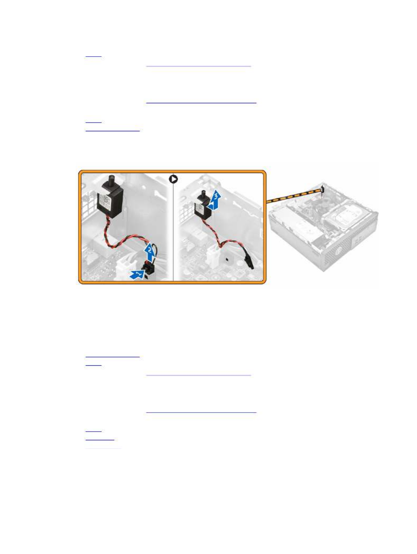
Removing the intrusion switch
1. Follow the procedure in .Before Working Inside Your Computer
2. Remove the:
a. cover
b. heat sink fan cover
3. To remove the intrusion switch:
a. Disconnect the intrusion switch cable from the connector on the system board [1, 2].
b. Slide the intrusion switch and lift it away from the computer [3].
Installing the intrusion switch
1. Insert the intrusion switch into the slot on the chassis.
2. Connect the intrusion switch cable to the system board.
3. Install the:
a. heat sink fan cover
b. cover
4. Follow the procedure in .After Working Inside Your Computer
Removing the memory module
1. Follow the procedure in .
Before Working Inside Your Computer
2. Remove the:
a. cover
b. hard drive
c. optical drive
3. To remove the memory module:
a. Press the memory module retention tabs on both sides of the memory module.
b. Lift the memory module from the memory module connector on the system board.
13

Installing the memory module
1. Align the notch on the memory module with the tab on the memory module connector.
2. Insert the memory module into the memory module socket.
3. Press the memory module until the memory module retention tabs click into place.
4. Install the:
a. optical drive
b. hard drive
c. cover
5. Follow the procedure in .After Working Inside Your Computer
Installing the optional PCIe SSD card
NOTE:
NOTE:
NOTE:
NOTE: NOTE: The PCIe SSD card is shipped with the following components:
1. PCIe SSD card
2. Thermal pad
3. Screw
1. Follow the procedure in Before Working Inside Your Computer
2. Remove the:
a. cover
b. hard drive
c. optical drive
3. Peel the adhesive tape (blue) from the rubber.
14
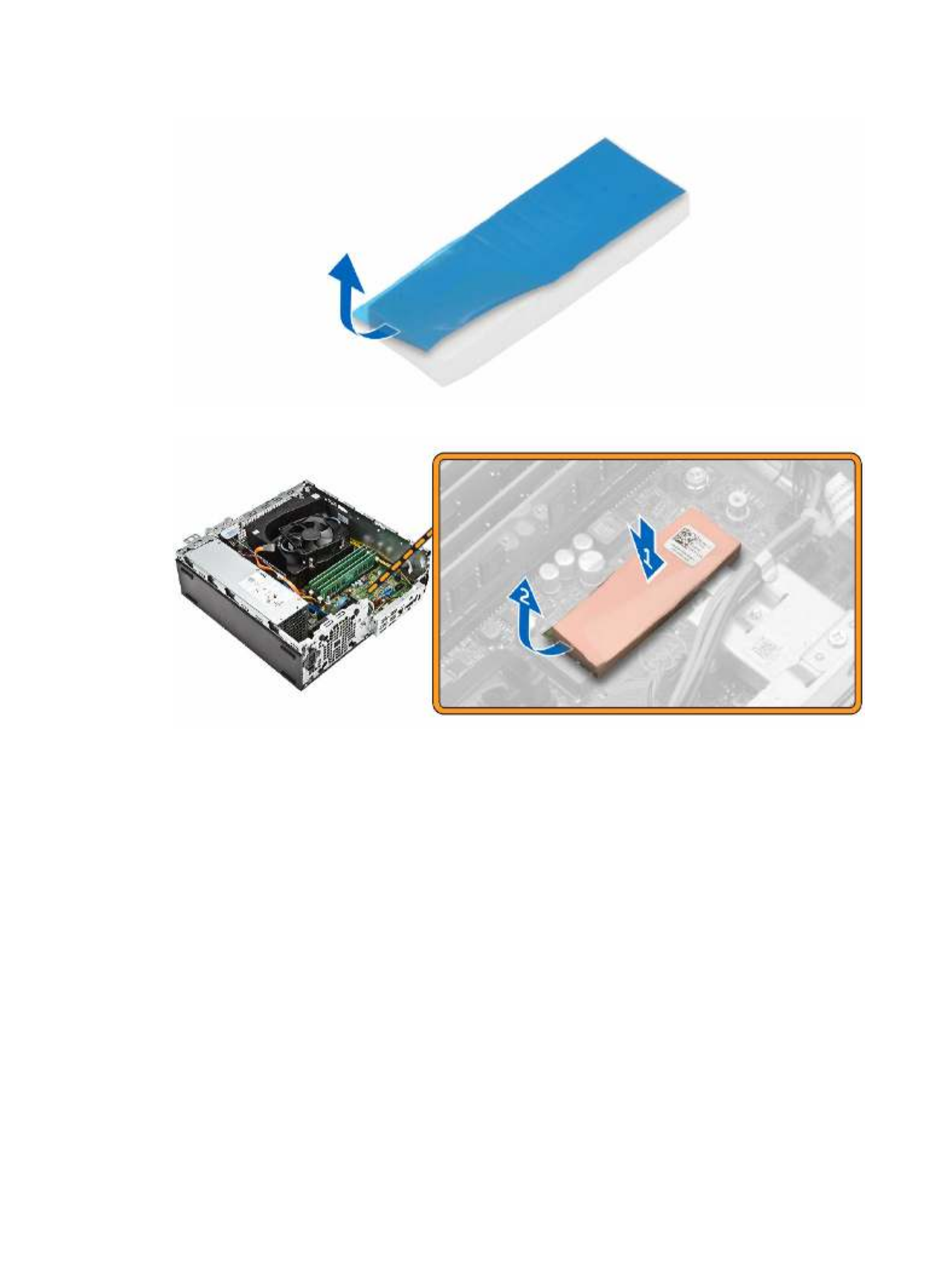
4. Place the rubber on the computer [1] and peel the adhesive tape (pink) from the rubber [2].
5. To install the SSD card:
a. Connect the SSD card to the connector on the system board [1].
b. Tighten the screw to secure the SSD card to the system board [2].
15

Removing the optional PCIe SSD card
1. Follow the procedure in .
After Working Inside Your Computer
2. Install the:
a. cover
b. hard drive
c. optical drive
3. Remove the screw that secures the PCIe SSD card to the system board.
4. Disconnect the PCIe SSD card from the connector on the system board.
5. Remove the rubber from the system board.
Removing the expansion card
1. Follow the procedure in . Before Working Inside Your Computer
2. Remove the .cover
3. To remove the expansion card:
a. Pull the metal tab to open the expansion card latch [1].
b. Pull the tab forward [2] and pull the expansion card from the connector on the computer [3].
16

Installing the expansion card
1. Insert the expansion card into the connector on the system board.
2. Press the expansion card until it clicks into place.
3. Close the expansion card latch and press it until it clicks into place.
4. Install the .
cover
5. Follow the procedure in .After Working Inside Your Computer
Removing the power supply unit (PSU)
1. Follow the procedure in .
Before Working Inside Your Computer
2. Remove:
a. cover
b. front bezel
c. hard drive
d. optical drive
e. heatsink fan cover
3. To release the PSU:
a. Disconnect the power cable from the system board [1, 2].
b. Unroute the power cables from the retention clips on the chassis [3}.
17

4. To remove the PSU:
a. Remove the screws at the back of the computer that secure the PSU to the computer [1].
b. Press the blue release tab [2] and lift the PSU away from the computer [3].
Installing the power supply unit (PSU)
1. Slide the PSU toward the back of the computer until it clicks into place.
2. Tighten the screws to secure the PSU to the computer.
3. Route the PSU cables through the retention clips.
4. Connect the PSU cables to their connectors on the system board.
5. Install the:
a. heat sink fan cover
18

b. optical drive
c. hard drive
d. front bezel
e. cover
6. Follow the procedure in .After Working Inside Your Computer
Removing the power button
1. Follow the procedure in .
Before Working Inside Your Computer
2. Remove the:
a. cover
b. front bezel
c. hard drive
d. optical drive
3. To remove the power button:
a. Disconnect the power switch cable from the system board [1].
b. Press the power switch retention tabs and remove it from the chassis [2, 3].
Installing the power button
1. Slide the power switch module into the slot on the chassis until it clicks into place.
2. Connect the power switch cable to the connector on the system board.
3. Install the:
a. optical drive
b. hard drive
c. front bezel
d. cover
4. Follow the procedure in .After Working Inside Your Computer
19

Removing the Input/Output (I/O) panel
1. Follow the procedure in .
Before Working Inside Your Computer
2. Remove the:
a. cover
b. front bezel
3. To remove the I/O panel:
a. Remove the screw that secures the I/O panel to the chassis [1].
b. Slide the I/O panel to the right and remove it from the computer [2].
Installing the Input/Output (I/O) panel
1. Insert the I/O panel on the chassis and slide it until it clicks into place.
2. Tighten the screws to secure the I/O panel to the chassis.
3. Install the:
a. front bezel
b. cover
4. Follow the procedure in .After Working Inside Your Computer
Removing the system fan
1. Follow the procedure in .
Before Working Inside Your Computer
2. Remove the:
a. cover
b. front bezel
c. hard drive
d. optical drive
3. To remove the system fan:
a. Disconnect the system fan cable from the system board [1].
b. Slide the fan grommets toward the slot on the back wall [2].
c. Lift the fan away from the computer [3].
20

Installing the system fan
1. Place the system fan in the computer.
2. Pass the grommets through the chassis and slide outward along the groove to secure it in place.
3. Connect the system fan cable to the system board.
4. Install the:
a. optical drive
b. hard drive
c. front bezel
d. cover
5. Follow the procedure in .After Working Inside Your Computer
Removing the heat sink fan cover
1. Follow the procedure in .
Before Working Inside Your Computer
2. Remove the .cover
3. To remove the fan duct:
a. Holding the touch points, pull the fan duct bracket to release the fan duct [1].
b. Lift the fan duct away from the computer [2].
21
Termékspecifikációk
| Márka: | Dell |
| Kategória: | Asztali |
| Modell: | PRECISION T3420 |
Szüksége van segítségre?
Ha segítségre van szüksége Dell PRECISION T3420, tegyen fel kérdést alább, és más felhasználók válaszolnak Önnek
Útmutatók Asztali Dell

12 Január 2025
7 Október 2024
2 Október 2024
21 Szeptember 2024
20 Szeptember 2024
17 Szeptember 2024
15 Szeptember 2024
8 Szeptember 2024
2 Szeptember 2024
1 Szeptember 2024
Útmutatók Asztali
- Asztali Samsung
- Asztali Sony
- Asztali Fujitsu
- Asztali Acer
- Asztali Sharkoon
- Asztali Sharp
- Asztali Lenovo
- Asztali Toshiba
- Asztali HP
- Asztali BenQ
- Asztali Apple
- Asztali Medion
- Asztali LC-Power
- Asztali Gigabyte
- Asztali Tripp Lite
- Asztali BDI
- Asztali Microsoft
- Asztali Asus
- Asztali Vtech
- Asztali PEAQ
- Asztali Haier
- Asztali Supermicro
- Asztali AOC
- Asztali Asrock
- Asztali Kobo
- Asztali Viewsonic
- Asztali MSI
- Asztali ZTE
- Asztali Kogan
- Asztali Mio
- Asztali Moxa
- Asztali Razer
- Asztali JYSK
- Asztali Vorago
- Asztali NEC
- Asztali Elo
- Asztali Axis
- Asztali ECS
- Asztali Planar
- Asztali Zotac
- Asztali Kramer
- Asztali Alienware
- Asztali Emachines
- Asztali Parisot
- Asztali Trekstor
- Asztali Maxdata
- Asztali Woood
- Asztali Wehkamp
- Asztali InFocus
- Asztali Intel
- Asztali Targa
- Asztali Seagate
- Asztali Shuttle
- Asztali VXL
- Asztali Promethean
- Asztali Foxconn
- Asztali Ibm
- Asztali Advantech
- Asztali MP
- Asztali Elitegroup
- Asztali Smart Things
- Asztali ONYX
- Asztali System76
- Asztali Zoostorm
- Asztali Bestar
- Asztali Pelco
- Asztali Cybernet
- Asztali Altra
- Asztali Dell Wyse
- Asztali AOpen
- Asztali NComputing
- Asztali MvixUSA
- Asztali Faytech
- Asztali AIS
- Asztali Wyse
- Asztali Kendall Howard
Legújabb útmutatók Asztali

9 Április 2025
2 Április 2025

1 Április 2025

30 Március 2025
28 Március 2025
18 Március 2025
13 Január 2025

12 Január 2025
12 Január 2025
12 Január 2025