Használati útmutató Dell Latitude 7480
Olvassa el alább 📖 a magyar nyelvű használati útmutatót Dell Latitude 7480 (83 oldal) a laptop kategóriában. Ezt az útmutatót 7 ember találta hasznosnak és 2 felhasználó értékelte átlagosan 4.5 csillagra
Oldal 1/83

Dell La
Dell La
Dell La
Dell LaDell Latitude 7
titude 7
titude 7
titude 7titude 7480
480
480
480480
Owner's Manual
Regulatory Model: P73G
Regulatory Model: P73G
Regulatory Model: P73G
Regulatory Model: P73GRegulatory Model: P73G
Regulatory T
Regulatory T
Regulatory T
Regulatory TRegulatory T
ype: P73G001
ype: P73G001
ype: P73G001
ype: P73G001ype: P73G001

Notes, cautions, and warnings
NOTE:
NOTE:
NOTE:
NOTE: NOTE: A NO
A NO
A NO
A NOA NOTE indicat
TE indicat
TE indicat
TE indicatTE indicates important inf
es important inf
es important inf
es important infes important information that helps y
ormation that helps y
ormation that helps y
ormation that helps yormation that helps you make bett
ou make bett
ou make bett
ou make bettou make better use of your pr
er use of your pr
er use of your pr
er use of your prer use of your product.
oduct.
oduct.
oduct.oduct.
CA
CA
CA
CACAUTION:
UTION:
UTION:
UTION: UTION: A CA
A CA
A CA
A CAA CAUTION indicat
UTION indicat
UTION indicat
UTION indicatUTION indicates either poten
es either poten
es either poten
es either potenes either potential damage to har
tial damage to har
tial damage to har
tial damage to hartial damage to hardwar
dwar
dwar
dwardware or loss of dat
e or loss of dat
e or loss of dat
e or loss of date or loss of data and tells you ho
a and tells you ho
a and tells you ho
a and tells you hoa and tells you how to a
w to a
w to a
w to aw to avoid the pr
void the pr
void the pr
void the prvoid the problem.
oblem.
oblem.
oblem.oblem.
W
W
W
WWARNING:
ARNING:
ARNING:
ARNING: ARNING: A WARNING indica
A WARNING indica
A WARNING indica
A WARNING indicaA WARNING indicates a pot
tes a pot
tes a pot
tes a pottes a potential f
ential f
ential f
ential fential for property damage
or property damage
or property damage
or property damageor property damage, personal injury
, personal injury
, personal injury
, personal injury, personal injury, or death.
, or death.
, or death.
, or death., or death.
© 2017 - 2018 Dell Inc. or it
© 2017 - 2018 Dell Inc. or it
© 2017 - 2018 Dell Inc. or it
© 2017 - 2018 Dell Inc. or it© 2017 - 2018 Dell Inc. or its subsidiaries. All rights r
s subsidiaries. All rights r
s subsidiaries. All rights r
s subsidiaries. All rights rs subsidiaries. All rights reserved.
eserved.
eserved.
eserved.eserved. Dell, EMC, and other trademarks are trademarks of Dell Inc. or its subsidiaries. Other
trademarks may be trademarks of their respective owners.
2018 - 12
Rev. A03

Con
Con
Con
ConCont
t
t
tten
en
en
enent
t
t
tts
s
s
ss
1 W
1 W
1 W
1 W1 Working on your comput
orking on your comput
orking on your comput
orking on your computorking on your computer............................................................................................................................. 7
er............................................................................................................................. 7
er............................................................................................................................. 7
er............................................................................................................................. 7er............................................................................................................................. 7
Turning your — Windows............................................................................................................................................7o
Turning your computer — Windows 8.......................................................................................................................7o
Turning your computer — Windows 7.......................................................................................................................7o
Before working inside your computer.............................................................................................................................. 7
Safety instructions............................................................................................................................................................. 8
After working inside your computer.................................................................................................................................8
2 Disassembly and r
2 Disassembly and r
2 Disassembly and r
2 Disassembly and r2 Disassembly and reassembly........................................................................................................................ 10
eassembly........................................................................................................................ 10
eassembly........................................................................................................................ 10
eassembly........................................................................................................................ 10eassembly........................................................................................................................ 10
Recommended tools........................................................................................................................................................ 10
Screw size list....................................................................................................................................................................10
Subscriber Module (SIM) card................................................................................................................. 11Identication
Removing SIM card or SIM card tray........................................................................................................................11
Replacing SIM card..................................................................................................................................................... 11
Removing dummy SIM card tray .............................................................................................................................. 11
Base cover.........................................................................................................................................................................12
Removing base cover.................................................................................................................................................12
Installing base cover................................................................................................................................................... 14
Battery............................................................................................................................................................................... 14
Lithium-ion battery precautions................................................................................................................................ 14
Removing battery....................................................................................................................................................... 14
Installing battery..........................................................................................................................................................15
PCIe Solid State Drive (SSD).......................................................................................................................................... 15
Removing PCIe SSD...................................................................................................................................................15
Installing PCIe SSD.....................................................................................................................................................16
Speaker.............................................................................................................................................................................. 17
Removing speaker module.........................................................................................................................................17
Installing speaker module...........................................................................................................................................18
Coin cell battery................................................................................................................................................................ 18
Removing the coin cell battery................................................................................................................................. 18
Installing coin cell battery...........................................................................................................................................19
WWAN card.......................................................................................................................................................................19
Removing WWAN card.............................................................................................................................................. 19
Installing WWAN card................................................................................................................................................20
WLAN card....................................................................................................................................................................... 20
Removing WLAN card...............................................................................................................................................20
Installing WLAN card..................................................................................................................................................21
Memory modules............................................................................................................................................................. 22
Removing memory module....................................................................................................................................... 22
Installing memory module..........................................................................................................................................22
Heat sink .......................................................................................................................................................................... 23
Removing heat sink assembly...................................................................................................................................23
Installing heat sink assembly.....................................................................................................................................23
Contents 3

LED board......................................................................................................................................................................... 24
Removing LED board.................................................................................................................................................24
Installing LED board................................................................................................................................................... 25
Smart card module.......................................................................................................................................................... 25
Removing smart card cage.......................................................................................................................................25
Installing smart card cage......................................................................................................................................... 26
Touchpad buttons board................................................................................................................................................. 27
Removing touchpad buttons board..........................................................................................................................27
Installing touchpad buttons board............................................................................................................................28
Power connector port..................................................................................................................................................... 28
Removing power connector port.............................................................................................................................28
Installing power connector port............................................................................................................................... 29
Display Assembly..............................................................................................................................................................29
Removing display assembly—with Touch...............................................................................................................30
Installing display assembly—with touch.................................................................................................................. 31
Display Bezel......................................................................................................................................................................31
Removing display bezel............................................................................................................................................. 32
Installing display bezel................................................................................................................................................32
LCD panel..........................................................................................................................................................................33
Removing LCD panel................................................................................................................................................. 33
Installing LCD panel....................................................................................................................................................34
Camera.............................................................................................................................................................................. 34
Removing camera...................................................................................................................................................... 35
Installing camera.........................................................................................................................................................35
Removing dummy SIM card tray....................................................................................................................................36
System board....................................................................................................................................................................36
Removing system board............................................................................................................................................36
Installing system board...............................................................................................................................................41
Keyboard............................................................................................................................................................................41
Removing keyboard assembly................................................................................................................................... 41
Removing keyboard from keyboard tray................................................................................................................. 43
Installing keyboard to keyboard tray........................................................................................................................ 43
Installing keyboard assembly.....................................................................................................................................43
Palm rest........................................................................................................................................................................... 44
Replacing palm rest .................................................................................................................................................. 44
5 Syst
5 Syst
5 Syst
5 Syst5 System Setup..............................................................................................................................................
em Setup..............................................................................................................................................
em Setup..............................................................................................................................................
em Setup..............................................................................................................................................em Setup..............................................................................................................................................46
46
46
4646
Boot menu........................................................................................................................................................................ 46
Navigation keys................................................................................................................................................................ 47
System setup options......................................................................................................................................................47
General screen options....................................................................................................................................................47
System Conguration screen options........................................................................................................................... 48
Video screen options.......................................................................................................................................................50
Security screen options.................................................................................................................................................. 50
Secure Boot screen options........................................................................................................................................... 52
Intel software guard extensions screen options...........................................................................................................53
Performance screen options.......................................................................................................................................... 53
4 Contents

Power management screen options..............................................................................................................................54
POST behavior screen options...................................................................................................................................... 55
Manageability................................................................................................................................................................... 56
Virtualization support screen options............................................................................................................................56
Wireless screen options.................................................................................................................................................. 56
Maintenance screen options...........................................................................................................................................57
System logs screen options............................................................................................................................................ 57
Updating the BIOS in Windows .................................................................................................................................... 58
Updating BIOS using USB drive........................................................................................................................... 58ash
System and setup password.......................................................................................................................................... 58
Assigning a system setup password........................................................................................................................59
Deleting or changing an existing system setup password.................................................................................... 59
4 Syst
4 Syst
4 Syst
4 Syst4 System
em
em
em em ..................................................................................................................................
..................................................................................................................................
..................................................................................................................................
....................................................................................................................................................................................................................................................................60
60
60
6060
specications
specications
specications
specicationsspecications
Supported operating systems........................................................................................................................................ 60
Processor ................................................................................................................................................. 60specications
System .......................................................................................................................................................61specications
Memory .....................................................................................................................................................61specications
Storage specications......................................................................................................................................................61
Video ..........................................................................................................................................................61specications
Audio .........................................................................................................................................................62specications
Battery ......................................................................................................................................................62specications
AC adapter specications............................................................................................................................................... 63
Docking options................................................................................................................................................................63
Port and connector specications.................................................................................................................................63
Communication ........................................................................................................................................64specications
Camera specications..................................................................................................................................................... 64
Touchpad ..................................................................................................................................................64specications
Display specications.......................................................................................................................................................64
Physical .....................................................................................................................................................66specications
Environmental .......................................................................................................................................... 67specications
5 Syst
5 Syst
5 Syst
5 Syst5 System Setup..............................................................................................................................................
em Setup..............................................................................................................................................
em Setup..............................................................................................................................................
em Setup..............................................................................................................................................em Setup..............................................................................................................................................68
68
68
6868
Boot Sequence.................................................................................................................................................................68
Navigation keys................................................................................................................................................................69
System setup options......................................................................................................................................................69
General screen options....................................................................................................................................................69
System Conguration screen options............................................................................................................................70
Video screen options....................................................................................................................................................... 72
Security screen options...................................................................................................................................................72
Secure Boot screen options............................................................................................................................................74
Intel software guard extensions screen options...........................................................................................................75
Performance screen options...........................................................................................................................................75
Power management screen options.............................................................................................................................. 76
POST behavior screen options.......................................................................................................................................77
Manageability....................................................................................................................................................................78
Virtualization support screen options............................................................................................................................ 78
Contents 5

Wireless screen options...................................................................................................................................................78
Maintenance screen options...........................................................................................................................................79
System logs screen options............................................................................................................................................ 79
Updating the BIOS in Windows .................................................................................................................................... 80
System and setup password.......................................................................................................................................... 80
Assigning a system setup password........................................................................................................................80
Deleting or changing an existing system setup password.....................................................................................81
6 T
6 T
6 T
6 T6 Tr
r
r
rroubleshooting...........................................................................................................................................
oubleshooting...........................................................................................................................................
oubleshooting...........................................................................................................................................
oubleshooting...........................................................................................................................................oubleshooting........................................................................................................................................... 82
82
82
8282
Enhanced Pre-Boot System Assessment — ePSA diagnostics................................................................................82
Running the ePSA Diagnostics.................................................................................................................................82
7 Contac
7 Contac
7 Contac
7 Contac7 Contacting Dell............................................................................................................................................
ting Dell............................................................................................................................................
ting Dell............................................................................................................................................
ting Dell............................................................................................................................................ting Dell............................................................................................................................................ 83
83
83
8383
6 Contents

W
W
W
WWorking on your comput
orking on your comput
orking on your comput
orking on your computorking on your computer
er
er
erer
T
T
T
TTurning
urning
urning
urning urning y
y
y
y your — Windows
our — Windows
our — Windows
our — Windowsour — Windows
o
o
o
oo
CA
CA
CA
CACAUTION:
UTION:
UTION:
UTION: UTION: T
T
T
TT
o avoid losing dat
o avoid losing dat
o avoid losing dat
o avoid losing dato avoid losing data, save and close all open
a, save and close all open
a, save and close all open
a, save and close all open a, save and close all open and exit all open pr
and exit all open pr
and exit all open pr
and exit all open pr and exit all open programs be
ograms be
ograms be
ograms beograms befor
for
for
forfore you turn
e you turn
e you turn
e you turn e you turn your comput
your comput
your comput
your comput your computer .
er .
er .
er .er .
les
les
les
lesles o
o
o
oo
1 Click or tap .
2 Click or tap and then click or tap .
Shut down
Shut down
Shut down
Shut downShut down
NOTE:
NOTE:
NOTE:
NOTE: NOTE: Ensur
Ensur
Ensur
EnsurEnsure that the comput
e that the comput
e that the comput
e that the compute that the computer and all attached devices ar
er and all attached devices ar
er and all attached devices ar
er and all attached devices arer and all attached devices are turned
e turned
e turned
e turned e turned If your comput
If your comput
If your comput
If your comput If your computer and attached de
er and attached de
er and attached de
er and attached deer and attached devices did not
vices did not
vices did not
vices did not vices did not
o.
o.
o.
o.o.
automa
automa
automa
automaautomatically turn
tically turn
tically turn
tically turn tically turn when you shut down your oper
when you shut down your oper
when you shut down your oper
when you shut down your oper when you shut down your operating syst
ating syst
ating syst
ating systating system, press and hold the pow
em, press and hold the pow
em, press and hold the pow
em, press and hold the powem, press and hold the power button f
er button f
er button f
er button fer button for about 6 seconds
or about 6 seconds
or about 6 seconds
or about 6 seconds or about 6 seconds
o
o
o
oo
to turn them
to turn them
to turn them
to turn them to turn them o
o
o
oo.
.
.
..
T
T
T
TTurning
urning
urning
urning urning y
y
y
y your comput
our comput
our comput
our computour computer — Windows 8
er — Windows 8
er — Windows 8
er — Windows 8er — Windows 8
o
o
o
oo
CA
CA
CA
CACAUTION
UTION
UTION
UTIONUTION:
:
:
: : T
T
T
TT
o avoid losing dat
o avoid losing dat
o avoid losing dat
o avoid losing dato avoid losing data, save and close all open
a, save and close all open
a, save and close all open
a, save and close all open a, save and close all open and exit all open pr
and exit all open pr
and exit all open pr
and exit all open pr and exit all open programs befor
ograms befor
ograms befor
ograms beforograms before you turn
e you turn
e you turn
e you turn e you turn your computer
your computer
your computer
your computer your computer
.
.
.
..
les
les
les
lesles o
o
o
oo
1 Turning o your computer:
• In Windows 8 (using a touch enabled device):
1 Swipe in from the right edge of the screen, opening the menu and select .
Charms
Charms
Charms
CharmsCharms Settings
Settings
Settings
SettingsSettings
2 Tap and then tap Shut down
Shut down
Shut down
Shut downShut down
• In Windows 8 (using a mouse):
1 Point to upper-right corner of the screen and click .
Settings
Settings
Settings
SettingsSettings
2 Click and then click .
Shut down
Shut down
Shut down
Shut downShut down
2 Ensure that the computer and all attached devices are turned If your computer and attached devices did not automatically turn o. o
when you shut down your operating system, press and hold the power button for about 6 seconds to turn them o.
T
T
T
TTurning
urning
urning
urning urning y
y
y
y your comput
our comput
our comput
our computour computer — Windows 7
er — Windows 7
er — Windows 7
er — Windows 7er — Windows 7
o
o
o
oo
CA
CA
CA
CACAUTION
UTION
UTION
UTIONUTION:
:
:
: : T
T
T
TT
o avoid losing dat
o avoid losing dat
o avoid losing dat
o avoid losing dato avoid losing data, save and close all open
a, save and close all open
a, save and close all open
a, save and close all open a, save and close all open and exit all open pr
and exit all open pr
and exit all open pr
and exit all open pr and exit all open programs befor
ograms befor
ograms befor
ograms beforograms before you turn
e you turn
e you turn
e you turn e you turn your computer
your computer
your computer
your computer your computer
.
.
.
..
les
les
les
lesles o
o
o
oo
1 Click .
Start
Start
Start
StartStart
2 Click .
Shut Down
Shut Down
Shut Down
Shut DownShut Down
NOTE
NOTE
NOTE
NOTENOTE:
:
:
: : Ensur
Ensur
Ensur
EnsurEnsure that the computer and all at
e that the computer and all at
e that the computer and all at
e that the computer and all ate that the computer and all attached devices ar
tached devices ar
tached devices ar
tached devices artached devices are turned
e turned
e turned
e turned e turned If your computer and a
If your computer and a
If your computer and a
If your computer and a If your computer and attached devices did not
ttached devices did not
ttached devices did not
ttached devices did not ttached devices did not
o.
o.
o.
o.o.
automa
automa
automa
automaautomatically turn
tically turn
tically turn
tically turn tically turn when you shut down your oper
when you shut down your oper
when you shut down your oper
when you shut down your oper when you shut down your operating syst
ating syst
ating syst
ating systating system, press and hold the pow
em, press and hold the pow
em, press and hold the pow
em, press and hold the powem, press and hold the power button f
er button f
er button f
er button fer button for about 6 seconds
or about 6 seconds
or about 6 seconds
or about 6 seconds or about 6 seconds
o
o
o
oo
to turn them
to turn them
to turn them
to turn them to turn them o
o
o
oo.
.
.
..
Bef
Bef
Bef
BefBefor
or
or
orore working inside y
e working inside y
e working inside y
e working inside ye working inside your comput
our comput
our comput
our computour computer
er
er
erer
1 Ensure that your work surface is and clean to prevent the computer cover from being scratched.at
2 Turn o your computer.
3 If the computer is connected to a docking device (docked), undock it.
4 Disconnect all network cables from the computer (if available).
1
1
1
11
Working on your computer 7

CA
CA
CA
CACAUTION:
UTION:
UTION:
UTION: UTION: If your comput
If your comput
If your comput
If your computIf your computer has an RJ45 port, disconnect the network cable b
er has an RJ45 port, disconnect the network cable b
er has an RJ45 port, disconnect the network cable b
er has an RJ45 port, disconnect the network cable ber has an RJ45 port, disconnect the network cable by
y
y
y y unplugging the cable fr
unplugging the cable fr
unplugging the cable fr
unplugging the cable fr unplugging the cable from your
om your
om your
om your om your
rst
rst
rst
rstrst
computer
computer
computer
computercomputer.
.
.
..
5 Disconnect your computer and all attached devices from their electrical outlets.
6 Open the display.
7 Press and hold the power button for few seconds, to ground the system board.
CA
CA
CA
CACAUTION:
UTION:
UTION:
UTION: UTION: T
T
T
TTo guar
o guar
o guar
o guaro guard against electrical shock unplug y
d against electrical shock unplug y
d against electrical shock unplug y
d against electrical shock unplug yd against electrical shock unplug your computer fr
our computer fr
our computer fr
our computer frour computer from the electrical outlet be
om the electrical outlet be
om the electrical outlet be
om the electrical outlet beom the electrical outlet befor
for
for
forfore performing S
e performing S
e performing S
e performing Se performing Step #
tep #
tep #
tep # tep #
8
8
8
88.
.
.
..
CA
CA
CA
CACAUTION:
UTION:
UTION:
UTION: UTION: T
T
T
TTo a
o a
o a
o ao avoid electr
void electr
void electr
void electrvoid electrosta
osta
osta
ostaostatic discharge
tic discharge
tic discharge
tic dischargetic discharge, ground y
, ground y
, ground y
, ground y, ground yourself by using a wrist gr
ourself by using a wrist gr
ourself by using a wrist gr
ourself by using a wrist grourself by using a wrist grounding strap or b
ounding strap or b
ounding strap or b
ounding strap or bounding strap or by periodically touching
y periodically touching
y periodically touching
y periodically touching y periodically touching
an unpaint
an unpaint
an unpaint
an unpaintan unpainted metal surf
ed metal surf
ed metal surf
ed metal surfed metal surface at the same time as touching a connec
ace at the same time as touching a connec
ace at the same time as touching a connec
ace at the same time as touching a connecace at the same time as touching a connector on the back of the comput
tor on the back of the comput
tor on the back of the comput
tor on the back of the computtor on the back of the computer
er
er
erer.
.
.
..
8 Remove any installed ExpressCards or Smart Cards from the appropriate slots.
Saf
Saf
Saf
SafSafety instructions
ety instructions
ety instructions
ety instructionsety instructions
Use the following safety guidelines to protect your computer from potential damage and to ensure your personal safety. Unless otherwise
noted, each procedure included in this document assumes that the following conditions exist:
• You have read the safety information that shipped with your computer.
• A component can be replaced or, if purchased separately, installed by performing the removal procedure in the reverse order.
W
W
W
WWARNING:
ARNING:
ARNING:
ARNING: ARNING: Disconnect all power sour
Disconnect all power sour
Disconnect all power sour
Disconnect all power sourDisconnect all power sources bef
ces bef
ces bef
ces befces befor
or
or
orore opening the computer cov
e opening the computer cov
e opening the computer cov
e opening the computer cove opening the computer cover or panels. A
er or panels. A
er or panels. A
er or panels. Aer or panels. After you
fter you
fter you
fter you fter you w
w
w
w working inside the
orking inside the
orking inside the
orking inside the orking inside the
nish
nish
nish
nishnish
computer
computer
computer
computercomputer, r
, r
, r
, r, replace all covers
eplace all covers
eplace all covers
eplace all coverseplace all covers, panels, and scr
, panels, and scr
, panels, and scr
, panels, and scr, panels, and screws bef
ews bef
ews bef
ews befews before connec
ore connec
ore connec
ore connecore connecting to the pow
ting to the pow
ting to the pow
ting to the powting to the power source
er source
er source
er sourceer source.
.
.
..
W
W
W
WWARNING:
ARNING:
ARNING:
ARNING: ARNING: Befor
Befor
Befor
BeforBefore working inside y
e working inside y
e working inside y
e working inside ye working inside your computer
our computer
our computer
our computerour computer, read the sa
, read the sa
, read the sa
, read the sa, read the safety in
fety in
fety in
fety infety information tha
formation tha
formation tha
formation thaformation that shipped with your computer
t shipped with your computer
t shipped with your computer
t shipped with your computert shipped with your computer. For additional
. For additional
. For additional
. For additional . For additional
saf
saf
saf
safsafety best prac
ety best prac
ety best prac
ety best pracety best practices informa
tices informa
tices informa
tices informatices information, see the Regulat
tion, see the Regulat
tion, see the Regulat
tion, see the Regulattion, see the Regulatory Compliance Homepage at www
ory Compliance Homepage at www
ory Compliance Homepage at www
ory Compliance Homepage at wwwory Compliance Homepage at www.dell.com/
.dell.com/
.dell.com/
.dell.com/.dell.com/r
r
r
rregulatory
egulatory
egulatory
egulatoryegulatory_compliance
_compliance
_compliance
_compliance _compliance
CA
CA
CA
CACAUTION:
UTION:
UTION:
UTION: UTION: Many r
Many r
Many r
Many rMany repairs ma
epairs ma
epairs ma
epairs maepairs may only be done by a
y only be done by a
y only be done by a
y only be done by a y only be done by a service technician. Y
service technician. Y
service technician. Y
service technician. Y service technician. You should only perform tr
ou should only perform tr
ou should only perform tr
ou should only perform trou should only perform troubleshooting and simple
oubleshooting and simple
oubleshooting and simple
oubleshooting and simple oubleshooting and simple
certied
certied
certied
certiedcertied
r
r
r
rrepairs as authorized in y
epairs as authorized in y
epairs as authorized in y
epairs as authorized in yepairs as authorized in your produc
our produc
our produc
our producour product documentation, or as dir
t documentation, or as dir
t documentation, or as dir
t documentation, or as dirt documentation, or as directed by the online or t
ected by the online or t
ected by the online or t
ected by the online or tected by the online or telephone service and support team.
elephone service and support team.
elephone service and support team.
elephone service and support team. elephone service and support team.
Damage due to servicing tha
Damage due to servicing tha
Damage due to servicing tha
Damage due to servicing thaDamage due to servicing that is not authorized b
t is not authorized b
t is not authorized b
t is not authorized bt is not authorized by Dell is not cover
y Dell is not cover
y Dell is not cover
y Dell is not covery Dell is not covered by your warr
ed by your warr
ed by your warr
ed by your warred by your warranty
anty
anty
antyanty. Read and f
. Read and f
. Read and f
. Read and f. Read and follow the saf
ollow the saf
ollow the saf
ollow the safollow the safety instructions
ety instructions
ety instructions
ety instructions ety instructions
that came with the pr
that came with the pr
that came with the pr
that came with the prthat came with the product.
oduct.
oduct.
oduct.oduct.
CA
CA
CA
CACAUTION:
UTION:
UTION:
UTION: UTION: T
T
T
TTo a
o a
o a
o ao avoid electr
void electr
void electr
void electrvoid electrostatic dischar
ostatic dischar
ostatic dischar
ostatic discharostatic discharge, gr
ge, gr
ge, gr
ge, grge, ground yourself by using a wrist gr
ound yourself by using a wrist gr
ound yourself by using a wrist gr
ound yourself by using a wrist ground yourself by using a wrist grounding strap or by periodically t
ounding strap or by periodically t
ounding strap or by periodically t
ounding strap or by periodically tounding strap or by periodically touching an
ouching an
ouching an
ouching an ouching an
unpaint
unpaint
unpaint
unpaintunpainted metal surf
ed metal surf
ed metal surf
ed metal surfed metal surface that is gr
ace that is gr
ace that is gr
ace that is grace that is grounded to gr
ounded to gr
ounded to gr
ounded to grounded to ground yourself be
ound yourself be
ound yourself be
ound yourself beound yourself befor
for
for
forfore you t
e you t
e you t
e you te you touch the computer t
ouch the computer t
ouch the computer t
ouch the computer touch the computer to perform any disassembly t
o perform any disassembly t
o perform any disassembly t
o perform any disassembly to perform any disassembly tasks.
asks.
asks.
asks.asks.
CA
CA
CA
CACAUTION:
UTION:
UTION:
UTION: UTION: Handle components and car
Handle components and car
Handle components and car
Handle components and carHandle components and cards with care. Do no
ds with care. Do no
ds with care. Do no
ds with care. Do nods with care. Do not touch the component
t touch the component
t touch the component
t touch the componentt touch the components or contact
s or contact
s or contact
s or contacts or contacts on a card. Hold a car
s on a card. Hold a car
s on a card. Hold a car
s on a card. Hold a cars on a card. Hold a card by its
d by its
d by its
d by its d by its
edges or by its me
edges or by its me
edges or by its me
edges or by its meedges or by its metal mounting br
tal mounting br
tal mounting br
tal mounting brtal mounting bracket. Hold a component such as a pr
acket. Hold a component such as a pr
acket. Hold a component such as a pr
acket. Hold a component such as a pracket. Hold a component such as a processor by its edges, not b
ocessor by its edges, not b
ocessor by its edges, not b
ocessor by its edges, not bocessor by its edges, not by its pins.
y its pins.
y its pins.
y its pins.y its pins.
CA
CA
CA
CACAUTION:
UTION:
UTION:
UTION: UTION: When you disconnect a cable
When you disconnect a cable
When you disconnect a cable
When you disconnect a cableWhen you disconnect a cable, pull on its connect
, pull on its connect
, pull on its connect
, pull on its connect, pull on its connector or on its pull-t
or or on its pull-t
or or on its pull-t
or or on its pull-tor or on its pull-tab, not on the cable itself
ab, not on the cable itself
ab, not on the cable itself
ab, not on the cable itselfab, not on the cable itself. Some cables have
. Some cables have
. Some cables have
. Some cables have . Some cables have
connect
connect
connect
connectconnectors with locking tabs; if y
ors with locking tabs; if y
ors with locking tabs; if y
ors with locking tabs; if yors with locking tabs; if you are disconnec
ou are disconnec
ou are disconnec
ou are disconnecou are disconnecting this type of cable, pr
ting this type of cable, pr
ting this type of cable, pr
ting this type of cable, prting this type of cable, press in on the locking tabs bef
ess in on the locking tabs bef
ess in on the locking tabs bef
ess in on the locking tabs befess in on the locking tabs befor
or
or
orore you disconnect the
e you disconnect the
e you disconnect the
e you disconnect the e you disconnect the
cable. As you pull connec
cable. As you pull connec
cable. As you pull connec
cable. As you pull conneccable. As you pull connectors apart, k
tors apart, k
tors apart, k
tors apart, ktors apart, keep them evenly aligned t
eep them evenly aligned t
eep them evenly aligned t
eep them evenly aligned teep them evenly aligned to avoid bending an
o avoid bending an
o avoid bending an
o avoid bending ano avoid bending any connector pins
y connector pins
y connector pins
y connector pinsy connector pins. Also, bef
. Also, bef
. Also, bef
. Also, bef. Also, before y
ore y
ore y
ore yore you connect a
ou connect a
ou connect a
ou connect a ou connect a
cable, ensur
cable, ensur
cable, ensur
cable, ensurcable, ensure that both connec
e that both connec
e that both connec
e that both connece that both connectors ar
tors ar
tors ar
tors artors are correctly orien
e correctly orien
e correctly orien
e correctly oriene correctly oriented and aligned.
ted and aligned.
ted and aligned.
ted and aligned.ted and aligned.
NOTE:
NOTE:
NOTE:
NOTE: NOTE: The color o
The color o
The color o
The color oThe color of your computer and cert
f your computer and cert
f your computer and cert
f your computer and certf your computer and certain components ma
ain components ma
ain components ma
ain components maain components may appear
y appear
y appear
y appear y appear dieren
dieren
dieren
dierendierently
tly
tly
tlytly than shown in this document.
than shown in this document.
than shown in this document.
than shown in this document. than shown in this document.
A
A
A
AAfter w
fter w
fter w
fter wfter working inside your comput
orking inside your comput
orking inside your comput
orking inside your computorking inside your computer
er
er
erer
After you complete any replacement procedure, ensure that you connect external devices, cards, and cables before turning on your
computer.
CA
CA
CA
CACAUTION
UTION
UTION
UTIONUTION:
:
:
: : T
T
T
TTo a
o a
o a
o ao avoid damage t
void damage t
void damage t
void damage tvoid damage to the computer
o the computer
o the computer
o the computero the computer, use only the batt
, use only the batt
, use only the batt
, use only the batt, use only the battery designed for this particular Dell comput
ery designed for this particular Dell comput
ery designed for this particular Dell comput
ery designed for this particular Dell computery designed for this particular Dell computer
er
er
erer. Do not use bat
. Do not use bat
. Do not use bat
. Do not use bat. Do not use batteries
teries
teries
teries teries
designed for o
designed for o
designed for o
designed for odesigned for other Dell computers
ther Dell computers
ther Dell computers
ther Dell computersther Dell computers.
.
.
..
1 Connect any external devices, such as a port replicator or media base, and replace any cards, such as an ExpressCard.
2 Connect any telephone or network cables to your computer.
CA
CA
CA
CACAUTION
UTION
UTION
UTIONUTION:
:
:
: : T
T
T
TTo connec
o connec
o connec
o conneco connect a network cable,
t a network cable,
t a network cable,
t a network cable, t a network cable, r
r
r
rrst
st
st
stst plug the cable into the ne
plug the cable into the ne
plug the cable into the ne
plug the cable into the ne plug the cable into the network device and then plug it int
twork device and then plug it int
twork device and then plug it int
twork device and then plug it inttwork device and then plug it into the
o the
o the
o the o the
computer
computer
computer
computercomputer.
.
.
..
3 Connect your computer and all attached devices to their electrical outlets.
8 Working on your computer

4 Turn on your computer.
Working on your computer 9

Disassembly and r
Disassembly and r
Disassembly and r
Disassembly and rDisassembly and reassembly
eassembly
eassembly
eassemblyeassembly
Recommended t
Recommended t
Recommended t
Recommended tRecommended tools
ools
ools
oolsools
The procedures in this document require the following tools:
• Phillips #0 screwdriver
• Phillips #1 screwdriver
• Small plastic scribe
Scr
Scr
Scr
ScrScrew siz
ew siz
ew siz
ew sizew size list
e list
e list
e liste list
T
T
T
TT
able 1. Latitude 7
able 1. Latitude 7
able 1. Latitude 7
able 1. Latitude 7able 1. Latitude 7480 - Screw siz
480 - Screw siz
480 - Screw siz
480 - Screw siz480 - Screw size list
e list
e list
e liste list
Component
Component
Component
ComponentComponent M2.
M2.
M2.
M2.M2.5x 6
5x 6
5x 6
5x 65x 6.
.
.
..0
0
0
00 M2.
M2.
M2.
M2.M2.5x5
5x5
5x5
5x55x5.
.
.
..0
0
0
00 M2.
M2.
M2.
M2.M2.0 x 5
0 x 5
0 x 5
0 x 50 x 5.
.
.
..0
0
0
00 M2.
M2.
M2.
M2.M2.5 x 4.
5 x 4.
5 x 4.
5 x 4.5 x 4.0
0
0
00 M2.0x
M2.0x
M2.0x
M2.0xM2.0x3
3
3
33.
.
.
..0
0
0
00 M2.
M2.
M2.
M2.M2.0 x 2.
0 x 2.
0 x 2.
0 x 2.0 x 2.5
5
5
55 M2.
M2.
M2.
M2.M2.0 x 2.
0 x 2.
0 x 2.
0 x 2.0 x 2.0
0
0
00
Back cover 8 (captive screw)
Battery (3-cell) 1
Battery (4-cell) 2
SSD module 1
Heat sink module 4
System fan 2 2
WWAN card 1
WLAN card 1
Power connector port 1
ESD bracket 2
EDP bracket 1
Touchpad buttons 2
Fingerprint reader 1
LED board 1
Smart card reader cage 2
Display hinge 6
Display panel • FHD - 2
• HD - 4
Keyboard support plate 18
Keyboard 5
System board 3
2
2
2
22
10 Disassembly and reassembly
Subscriber
Subscriber
Subscriber
Subscriber Subscriber Identica
Identica
Identica
IdenticaIdentication
tion
tion
tiontion Module (
Module (
Module (
Module ( Module (SIM) car
SIM) car
SIM) car
SIM) carSIM) card
d
d
dd
Remo
Remo
Remo
RemoRemoving SIM car
ving SIM car
ving SIM car
ving SIM carving SIM card or SIM car
d or SIM car
d or SIM car
d or SIM card or SIM card tr
d tr
d tr
d trd tra
a
a
aay
y
y
yy
NOTE:
NOTE:
NOTE:
NOTE: NOTE: SIM car
SIM car
SIM car
SIM carSIM card or SIM car
d or SIM car
d or SIM car
d or SIM card or SIM card tray r
d tray r
d tray r
d tray rd tray removal is only a
emoval is only a
emoval is only a
emoval is only aemoval is only available on syst
vailable on syst
vailable on syst
vailable on systvailable on systems that are shipped with WW
ems that are shipped with WW
ems that are shipped with WW
ems that are shipped with WWems that are shipped with WWAN module. Hence, r
AN module. Hence, r
AN module. Hence, r
AN module. Hence, rAN module. Hence, removing
emoving
emoving
emoving emoving
pr
pr
pr
prprocedure is only applicable f
ocedure is only applicable f
ocedure is only applicable f
ocedure is only applicable focedure is only applicable for systems that ar
or systems that ar
or systems that ar
or systems that aror systems that are shipped with WW
e shipped with WW
e shipped with WW
e shipped with WWe shipped with WWAN module.
AN module.
AN module.
AN module.AN module.
CA
CA
CA
CACAUTION:
UTION:
UTION:
UTION: UTION: Removing the SIM car
Removing the SIM car
Removing the SIM car
Removing the SIM carRemoving the SIM card when the computer is On, ma
d when the computer is On, ma
d when the computer is On, ma
d when the computer is On, mad when the computer is On, may cause data loss or damage the car
y cause data loss or damage the car
y cause data loss or damage the car
y cause data loss or damage the cary cause data loss or damage the card. Ensure that y
d. Ensure that y
d. Ensure that y
d. Ensure that yd. Ensure that your
our
our
our our
computer is turned
computer is turned
computer is turned
computer is turned computer is turned o
o
o
oo
or the network connections ar
or the network connections ar
or the network connections ar
or the network connections ar or the network connections are disabled.
e disabled.
e disabled.
e disabled.e disabled.
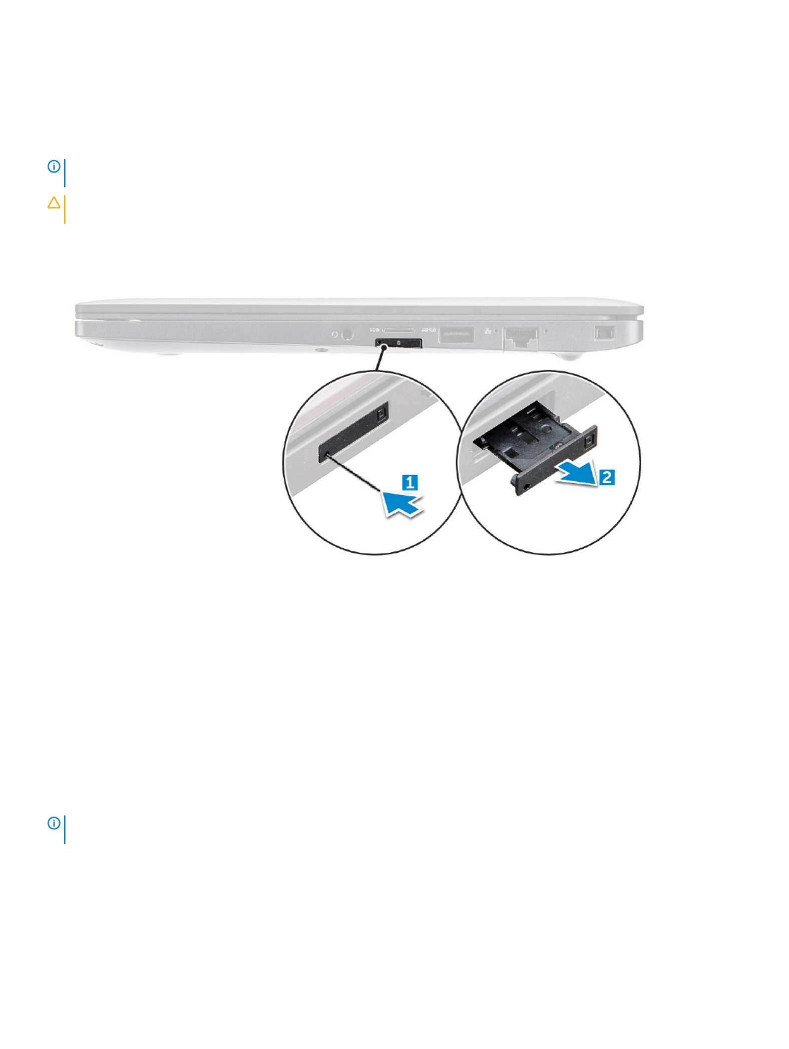
1 Insert a paperclip or a SIM card removal tool into the pinhole on the SIM card tray [1].
2 Use a scribe to pull the SIM card tray
3 Remove the SIM card, if a SIM card is available from the SIM card tray.
Replacing SIM car
Replacing SIM car
Replacing SIM car
Replacing SIM carReplacing SIM card
d
d
dd
1 Insert a paperclip or a SIM card removal tool into the pinhole on the SIM card tray.
2 Use a scribe to pull the SIM card tray
3 Place on the SIM card on the tray.
4 Insert the SIM card tray into the slot.
Remo
Remo
Remo
RemoRemoving dummy SIM car
ving dummy SIM car
ving dummy SIM car
ving dummy SIM carving dummy SIM card tra
d tra
d tra
d trad tray
y
y
y y
For models shipped with a WWAN card, the SIM card tray must be removed from the system before removing the system board. To rst
remove the SIM card tray from the system follow the steps outlined in the disassembly section.
NOTE
NOTE
NOTE
NOTENOTE:
:
:
: : For models shipped with a wir
For models shipped with a wir
For models shipped with a wir
For models shipped with a wirFor models shipped with a wireless card only
eless card only
eless card only
eless card onlyeless card only, a dummy SIM car
, a dummy SIM car
, a dummy SIM car
, a dummy SIM car, a dummy SIM card tra
d tra
d tra
d trad tray must
y must
y must
y must y must be r
be r
be r
be r be removed fr
emoved fr
emoved fr
emoved fremoved from the system bef
om the system bef
om the system bef
om the system befom the system before
ore
ore
ore ore
rst
rst
rst
rstrst
r
r
r
rremoving the system boar
emoving the system boar
emoving the system boar
emoving the system boaremoving the system board. The follo
d. The follo
d. The follo
d. The follod. The following are the st
wing are the st
wing are the st
wing are the stwing are the steps for r
eps for r
eps for r
eps for reps for removing the dummy SIM car
emoving the dummy SIM car
emoving the dummy SIM car
emoving the dummy SIM caremoving the dummy SIM card tray:
d tray:
d tray:
d tray:d tray:
1 Push the release latch on the SIM card slot inwards.
Disassembly and reassembly 11

2 Slide the dummy SIM card tray out of the system.
Base cov
Base cov
Base cov
Base covBase cover
er
er
erer
Remo
Remo
Remo
RemoRemoving base cov
ving base cov
ving base cov
ving base covving base cover
er
er
erer
1 Follow the procedure in Before working inside your computer.
2 To release the base cover:
a Loosen the M2.5 x 6.0 captive screws (8) that secure the base cover to the computer [1].
Remember
Remember
Remember
RememberRemember:
:
:
: : Exer
Exer
Exer
ExerExercise caution when loosening the scr
cise caution when loosening the scr
cise caution when loosening the scr
cise caution when loosening the scrcise caution when loosening the screws. Angle the scr
ews. Angle the scr
ews. Angle the scr
ews. Angle the screws. Angle the screw driver t
ew driver t
ew driver t
ew driver tew driver to mat
o mat
o mat
o mato match the head of the
ch the head of the
ch the head of the
ch the head of the ch the head of the
scr
scr
scr
scrscrew to a
ew to a
ew to a
ew to aew to avoid a possible stripped scr
void a possible stripped scr
void a possible stripped scr
void a possible stripped scrvoid a possible stripped screw head.
ew head.
ew head.
ew head.ew head.
b Use a plastic scribe to release the base cover from the edge and lift it from the computer [2].
12 Disassembly and reassembly
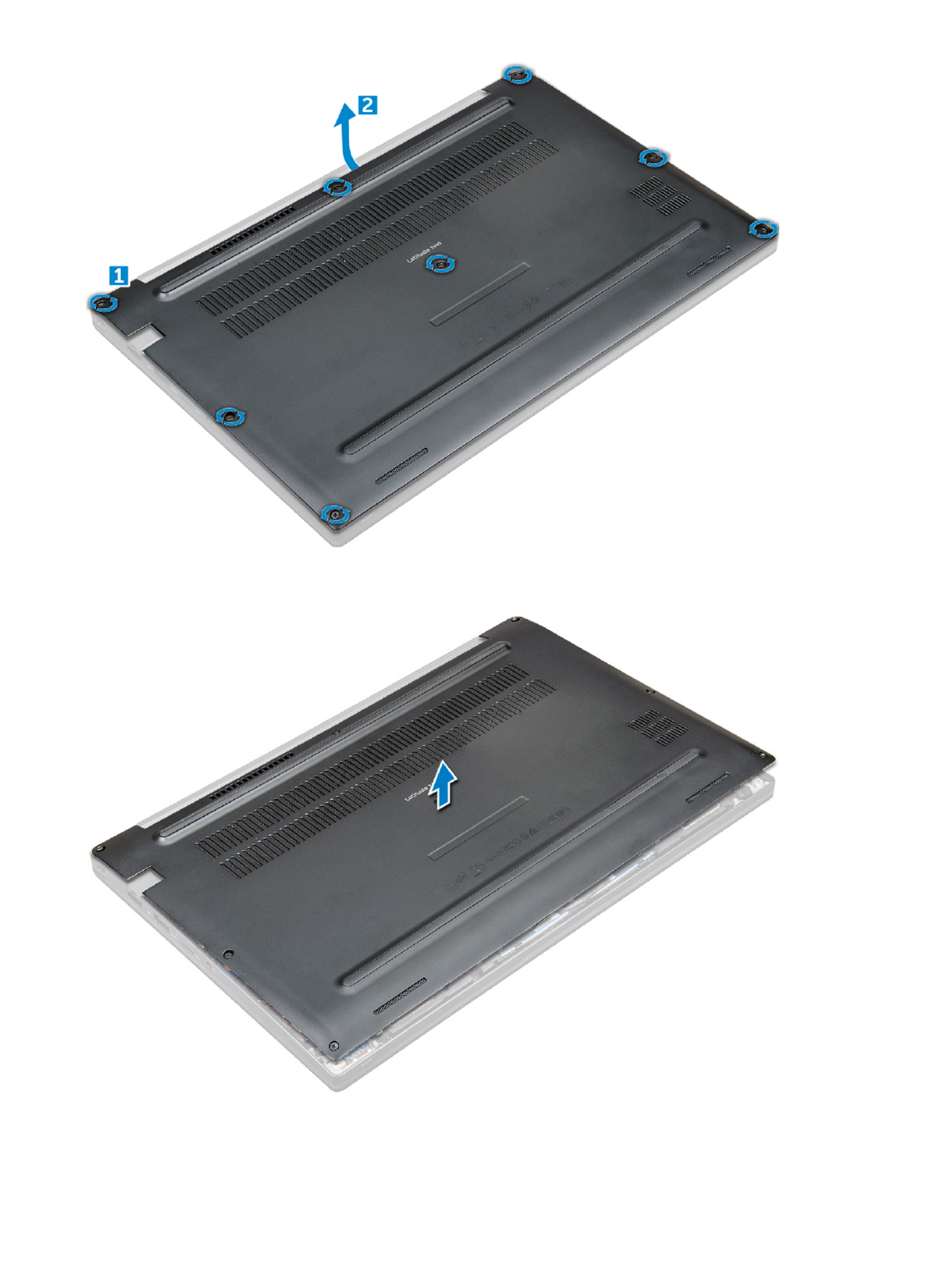
3 Lift the base cover from the computer.
Disassembly and reassembly 13

Installing base co
Installing base co
Installing base co
Installing base coInstalling base cover
ver
ver
verver
1 Align the base cover tabs to the slots on the edges of the computer.
2 Press the edges of the cover until it clicks into place.
3 Tighten the M2.5 x 6.0 captive screws to secure the base cover to the computer.
Remember:
Remember:
Remember:
Remember: Remember: Exer
Exer
Exer
ExerExercise caution when tight
cise caution when tight
cise caution when tight
cise caution when tightcise caution when tightening the scre
ening the scre
ening the scre
ening the screening the screws. Angle the scr
ws. Angle the scr
ws. Angle the scr
ws. Angle the scrws. Angle the screw driver t
ew driver t
ew driver t
ew driver tew driver to match the head o
o match the head o
o match the head o
o match the head oo match the head of the screw t
f the screw t
f the screw t
f the screw tf the screw to
o
o
o o
av
av
av
avavoid a possible stripped scre
oid a possible stripped scre
oid a possible stripped scre
oid a possible stripped screoid a possible stripped screw head.
w head.
w head.
w head.w head.
4 Follow the procedure in After working inside your computer.
Bat
Bat
Bat
BatBatt
t
t
ttery
ery
ery
eryery
Lithium-ion ba
Lithium-ion ba
Lithium-ion ba
Lithium-ion baLithium-ion batt
tt
tt
ttttery pr
ery pr
ery pr
ery prery precautions
ecautions
ecautions
ecautionsecautions
CA
CA
CA
CACAUTION:
UTION:
UTION:
UTION: UTION:
• Exercise caution when handling Lithium-ion batteries.
• Discharge the battery as much as possible before removing it from the system. This can be done by disconnecting the AC adapter
from the system to allow the battery to drain.
• Do not crush, drop, mutilate, or penetrate the battery with foreign objects.
• Do not expose the battery to high temperatures, or disassemble battery packs and cells.
• Do not apply pressure to the surface of the battery.
• Do not bend the battery.
• Do not use tools of any kind to pry on or against the battery.
• If a battery gets stuck in a device as a result of swelling, do not try to free it as puncturing, bending, or crushing a Lithium-ion
battery can be dangerous. In such an instance, the entire system should be replaced. Contact https://www.dell.com/support for
assistance and further instructions.
• Always purchase genuine batteries from https://www.dell.com or authorized Dell partners and re-sellers.
Remo
Remo
Remo
RemoRemoving bat
ving bat
ving bat
ving batving batt
t
t
ttery
ery
ery
eryery
1 Follow the procedure in Before working inside your computer.
2 Remove the .base cover
3 To remove the battery:
a Disconnect the battery cable from the connector on the system board [1].
b Remove the M2.0 x 5.0 screws that secure the battery to the computer [2].
NOTE
NOTE
NOTE
NOTENOTE:
:
:
: : A 3-cell batt
A 3-cell batt
A 3-cell batt
A 3-cell battA 3-cell battery has a single scre
ery has a single scre
ery has a single scre
ery has a single screery has a single screw
w
w
ww, and a 4-cell battery has tw
, and a 4-cell battery has tw
, and a 4-cell battery has tw
, and a 4-cell battery has tw, and a 4-cell battery has two screws
o screws
o screws
o screwso screws. Hence, the image display
. Hence, the image display
. Hence, the image display
. Hence, the image display. Hence, the image displayed
ed
ed
ed ed
below is a 4-cell bat
below is a 4-cell bat
below is a 4-cell bat
below is a 4-cell batbelow is a 4-cell battery
tery
tery
terytery.
.
.
..
c Lift the battery from the computer [3].
14 Disassembly and reassembly

Installing ba
Installing ba
Installing ba
Installing baInstalling batt
tt
tt
ttttery
ery
ery
eryery
1 Insert the battery into the slot on the computer.
2 Route the battery cable through the routing clip and connect the battery cable to the connector on the system board.
NOTE
NOTE
NOTE
NOTENOTE:
:
:
: : Rout
Rout
Rout
RoutRoute the batt
e the batt
e the batt
e the batte the battery cable, if the cable at the base of the bat
ery cable, if the cable at the base of the bat
ery cable, if the cable at the base of the bat
ery cable, if the cable at the base of the batery cable, if the cable at the base of the battery is un r
tery is un r
tery is un r
tery is un rtery is un routed.
outed.
outed.
outed.outed.
3 Tighten the M2.0 x 5.0 screws to secure the battery to the computer.
NOTE
NOTE
NOTE
NOTENOTE:
:
:
: : A small batt
A small batt
A small batt
A small battA small battery (3-cell) has a single scr
ery (3-cell) has a single scr
ery (3-cell) has a single scr
ery (3-cell) has a single screry (3-cell) has a single screw
ew
ew
ewew, a larger ba
, a larger ba
, a larger ba
, a larger ba, a larger battery (
ttery (
ttery (
ttery (ttery (4-cell) has two scr
4-cell) has two scr
4-cell) has two scr
4-cell) has two scr4-cell) has two screws
ews
ews
ewsews.
.
.
..
4 Install the base cover
5 Follow the procedure in After working inside your computer.
PCIe Solid St
PCIe Solid St
PCIe Solid St
PCIe Solid StPCIe Solid Sta
a
a
aat
t
t
tte Drive (
e Drive (
e Drive (
e Drive (e Drive (SSD
SSD
SSD
SSDSSD)
)
)
))
Remo
Remo
Remo
RemoRemoving PCIe SSD
ving PCIe SSD
ving PCIe SSD
ving PCIe SSDving PCIe SSD
1 Follow the procedure in Before working inside your computer.
2 Remove the :
abase cover
bbattery
3 To remove the PCIe SSD:
a Loosen the M2.0x3.0 captive screw that secure the SSD bracket [1].
b Remove the SSD bracket [2].
Disassembly and reassembly 15

NOTE:
NOTE:
NOTE:
NOTE: NOTE: Ensur
Ensur
Ensur
EnsurEnsure to r
e to r
e to r
e to re to remove the SSD br
emove the SSD br
emove the SSD br
emove the SSD bremove the SSD bracket, if the syst
acket, if the syst
acket, if the syst
acket, if the systacket, if the system is shipped with bracke
em is shipped with bracke
em is shipped with bracke
em is shipped with brackeem is shipped with bracket.
t.
t.
t.t.
c Remove the PCIe SSD from the connector on the system board [3].
Installing PCIe SSD
Installing PCIe SSD
Installing PCIe SSD
Installing PCIe SSDInstalling PCIe SSD
1 Insert the PCIe SSD card into the connector.
2 Install the SSD bracket over the PCIe SSD card.
NOTE
NOTE
NOTE
NOTENOTE:
:
:
: : When installing the SSD br
When installing the SSD br
When installing the SSD br
When installing the SSD brWhen installing the SSD bracket, ensur
acket, ensur
acket, ensur
acket, ensuracket, ensure that the tab on the brack
e that the tab on the brack
e that the tab on the brack
e that the tab on the bracke that the tab on the bracket is held securely with the t
et is held securely with the t
et is held securely with the t
et is held securely with the tet is held securely with the tab on the palm
ab on the palm
ab on the palm
ab on the palm ab on the palm
r
r
r
rrest.
est.
est.
est.est.
NOTE:
NOTE:
NOTE:
NOTE: NOTE: Ensur
Ensur
Ensur
EnsurEnsure to inst
e to inst
e to inst
e to inste to install the bracket is the s
all the bracket is the s
all the bracket is the s
all the bracket is the sall the bracket is the system is shipped with brack
ystem is shipped with brack
ystem is shipped with brack
ystem is shipped with brackystem is shipped with bracket.
et.
et.
et.et.
3 Tighten the M2.0x3.0 screws to secure it the SSD bracket.
4 Install the base cover.
5 Follow the procedure in After working iinside your computer.
16 Disassembly and reassembly

Speaker
Speaker
Speaker
SpeakerSpeaker
Remo
Remo
Remo
RemoRemoving speaker module
ving speaker module
ving speaker module
ving speaker moduleving speaker module
1 Follow the procedure in Before working inside your computer.
2 Remove the:
abase cover
bbattery
3 To release the speaker module:
a Push the pin to disconnect the speaker cable from the connector on the system board [1].
NOTE:
NOTE:
NOTE:
NOTE: NOTE: Ensur
Ensur
Ensur
EnsurEnsure to unr
e to unr
e to unr
e to unre to unrout
out
out
outoute the speaker cable fr
e the speaker cable fr
e the speaker cable fr
e the speaker cable fre the speaker cable from the routing clip
om the routing clip
om the routing clip
om the routing clipom the routing clip.
.
.
..
NOTE:
NOTE:
NOTE:
NOTE: NOTE: Use a plastic scribe t
Use a plastic scribe t
Use a plastic scribe t
Use a plastic scribe tUse a plastic scribe to release the cable fr
o release the cable fr
o release the cable fr
o release the cable fro release the cable from the connect
om the connect
om the connect
om the connectom the connector
or
or
oror. Do not pull the cable as it ma
. Do not pull the cable as it ma
. Do not pull the cable as it ma
. Do not pull the cable as it ma. Do not pull the cable as it may result in
y result in
y result in
y result in y result in
br
br
br
brbreakage.
eakage.
eakage.
eakage.eakage.
b Un-route the speaker cable from the routing clips [2,3].
c Remove the tape that secures the speaker cables to the touchpad board [4].
4 To remove the speaker module:
a Remove the M2.0x3.0 screws (4) that secure the speaker module to the computer [1].
b Lift the speaker module from the computer .
NOTE
NOTE
NOTE
NOTENOTE:
:
:
: : Ensur
Ensur
Ensur
EnsurEnsure to un-r
e to un-r
e to un-r
e to un-re to un-route the speaker cable fr
oute the speaker cable fr
oute the speaker cable fr
oute the speaker cable froute the speaker cable from the routing clips.
om the routing clips.
om the routing clips.
om the routing clips.om the routing clips.
Disassembly and reassembly 17
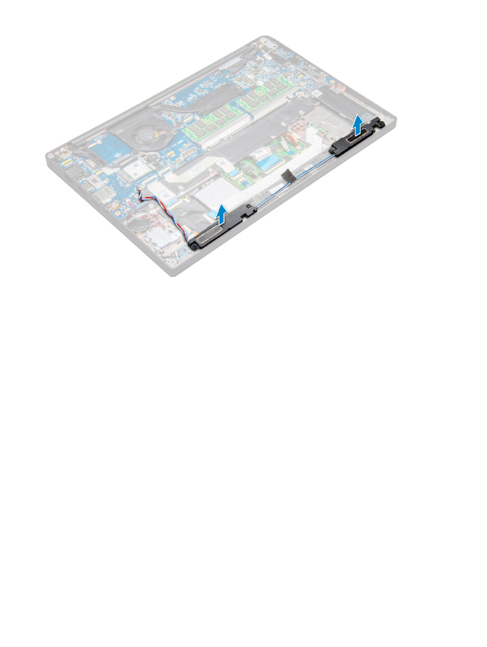
Installing speak
Installing speak
Installing speak
Installing speakInstalling speaker module
er module
er module
er moduleer module
1 Place the speaker module into the slots on the computer.
2 Route the speaker cable through the retention clips on the computer.
3 Connect the speaker cable to the connector on the system board.
4 Install the:
abattery
bbase cover
5 Follow the procedure in After working inside your computer.
Coin cell bat
Coin cell bat
Coin cell bat
Coin cell batCoin cell battery
tery
tery
terytery
Remo
Remo
Remo
RemoRemoving the coin cell bat
ving the coin cell bat
ving the coin cell bat
ving the coin cell batving the coin cell batt
t
t
ttery
ery
ery
eryery
1 Follow the procedure in Before working inside your computer.
2 Remove the :
abase cover
bbattery
3 To remove the coin cell battery:
a Disconnect the coin cell battery cable from the connector on the system board [1].
b Lift the coin cell battery to release it from the adhesive [2].
18 Disassembly and reassembly

Installing coin cell ba
Installing coin cell ba
Installing coin cell ba
Installing coin cell baInstalling coin cell batt
tt
tt
ttttery
ery
ery
eryery
1 Ax the coin cell battery on the slot inside the computer.
2 Route the coin cell battery cable through the routing channel before connecting the cable.
3 Connect the coin cell battery cable to the connector on the system board.
4 Install the :
abattery
bbase cover
5 Follow the procedure in After working inside your computer.
WW
WW
WW
WWWWAN car
AN car
AN car
AN carAN card
d
d
dd
Remo
Remo
Remo
RemoRemoving WW
ving WW
ving WW
ving WWving WWAN car
AN car
AN car
AN carAN card
d
d
dd
1 Follow the procedure in Before working inside your computer.
2 Remove the :
abase cover
bbattery
3 To remove the WWAN card:
a Remove the M2.0 x 3.0 screw that secures the metal bracket to the WWAN card .
b Lift the metal bracket that secures the WWAN card .
Disassembly and reassembly 19

c Disconnect the WWAN cables from the connectors on the WWAN card with a plastic scribe..
d .
Installing WW
Installing WW
Installing WW
Installing WWInstalling WWAN car
AN car
AN car
AN carAN card
d
d
dd
1 Insert the WWAN card into the connector on the system board.
2 Connect the WWAN cables to the connectors on the WWAN card.
3 Place the metal bracket and tighten the M2.0 x 3.0 screw to secure it to the computer.
4 Install the :
abattery
bbase cover
5 Follow the procedure in After working inside your computer.
NOTE
NOTE
NOTE
NOTENOTE:
:
:
: : The IMEI number can also be found on the WW
The IMEI number can also be found on the WW
The IMEI number can also be found on the WW
The IMEI number can also be found on the WWThe IMEI number can also be found on the WWAN car
AN car
AN car
AN carAN card.
d.
d.
d.d.
WL
WL
WL
WLWLAN car
AN car
AN car
AN carAN card
d
d
dd
Remo
Remo
Remo
RemoRemoving WL
ving WL
ving WL
ving WLving WLAN car
AN car
AN car
AN carAN card
d
d
dd
1 Follow the procedure in Before working inside your computer.
2 Remove the :
abase cover
20 Disassembly and reassembly

bbattery
3 To remove the WLAN card:
a Remove the M2.0 x 3.0 screw that secures the metal bracket to the WLAN card [1].
b Lift the metal bracket [2].
c Disconnect the WLAN cables from the connectors on the WLAN card [3].
d Remove the WLAN card from the computer [4].
NOTE:
NOTE:
NOTE:
NOTE: NOTE: Ensur
Ensur
Ensur
EnsurEnsure NO
e NO
e NO
e NOe NOT to pull the WLAN card mor
T to pull the WLAN card mor
T to pull the WLAN card mor
T to pull the WLAN card morT to pull the WLAN card more than 35
e than 35
e than 35
e than 35e than 35°
°
°
°°
, to a
, to a
, to a
, to a, to avoid damage to pin.
void damage to pin.
void damage to pin.
void damage to pin.void damage to pin.
Installing WLAN car
Installing WLAN car
Installing WLAN car
Installing WLAN carInstalling WLAN card
d
d
dd
1 Insert the WLAN card into the connector on the system board.
2 Connect the WLAN cables to the connectors on the WLAN card.
3 Place the metal bracket and tighten the M2.0 x 3.0 screw to secure it to the computer.
4 Install the .:
abattery
bbase cover
5 Follow the procedure in After working inside your computer.
Disassembly and reassembly 21

Memory modules
Memory modules
Memory modules
Memory modulesMemory modules
Remo
Remo
Remo
RemoRemoving memory module
ving memory module
ving memory module
ving memory moduleving memory module
1 Follow the procedure in Before working inside your computer.
2 Remove the :
abase cover
bbattery
3 To remove the memory module:
a Pull the clips securing the memory module until the module snaps-out [1].
b Remove the memory module from the connector on the system board [2].
Installing memory module
Installing memory module
Installing memory module
Installing memory moduleInstalling memory module
1 Insert the memory module into the connector until snaps in.
2 Install the :
abattery
bbase cover
3 Follow the procedures in After working inside your computer.
22 Disassembly and reassembly

Heat sink
Heat sink
Heat sink
Heat sink Heat sink
Remo
Remo
Remo
RemoRemoving heat sink assembly
ving heat sink assembly
ving heat sink assembly
ving heat sink assemblyving heat sink assembly
Heat sink assembly comprises of heat sink and the system fan.
1 Follow the procedure in Before working inside your computer.
2 Remove the:
abase cover
bbattery
3 To remove the heat sink assembly:
NOTE:
NOTE:
NOTE:
NOTE: NOTE: T
T
T
TT
o iden
o iden
o iden
o ideno identify the number of scr
tify the number of scr
tify the number of scr
tify the number of scrtify the number of screws, see .
ews, see .
ews, see .
ews, see .ews, see .scr
scr
scr
scrscrew list
ew list
ew list
ew listew list.
.
.
..
a Disconnect the fan cable from the system board [1].
b Remove the M2.0 x 5.0 screws that secure the heat sink assembly to the system board [2].
c Remove the screws in the order of the callout numbers as indicated on the heat sink.
d Lift the heat sink assembly from the system board [3].
Installing hea
Installing hea
Installing hea
Installing heaInstalling heat sink assembly
t sink assembly
t sink assembly
t sink assemblyt sink assembly
Heat sink assembly comprises of heat sink and the system fan.
1 Align the heat sink assembly with screw holders on the system board .
2 Tighten the M2.0 x 3.0 screws to secure the heat sink assembly to the system board.
NOTE
NOTE
NOTE
NOTENOTE:
:
:
: : Tight
Tight
Tight
TightTighten the scre
en the scre
en the scre
en the screen the screws in the order of the callout number
ws in the order of the callout number
ws in the order of the callout number
ws in the order of the callout numberws in the order of the callout numbers [1, 2, 3
s [1, 2, 3
s [1, 2, 3
s [1, 2, 3s [1, 2, 3, 4] as indicated on the hea
, 4] as indicated on the hea
, 4] as indicated on the hea
, 4] as indicated on the hea, 4] as indicated on the heat sink.
t sink.
t sink.
t sink.t sink.
Disassembly and reassembly 23

3 Connect the fan cable to the connector on the system board.
4 Install the :
abattery
bbase cover
5 Follow the procedure in After working inside your computer.
LED boar
LED boar
LED boar
LED boarLED board
d
d
dd
Remo
Remo
Remo
RemoRemoving LED boar
ving LED boar
ving LED boar
ving LED boarving LED board
d
d
dd
1 Follow the procedure in Before working inside your computer.
2 Remove the :
abase cover
bbattery
3 To remove the LED board:
a Disconnect the LED cable from the LED board [1].
CA
CA
CA
CACAUTION:
UTION:
UTION:
UTION: UTION: A
A
A
AAvoid pulling the cable as it w
void pulling the cable as it w
void pulling the cable as it w
void pulling the cable as it wvoid pulling the cable as it would r
ould r
ould r
ould rould result in br
esult in br
esult in br
esult in bresult in breaking the cable connect
eaking the cable connect
eaking the cable connect
eaking the cable connecteaking the cable connector
or
or
oror. Instead, use a scribe t
. Instead, use a scribe t
. Instead, use a scribe t
. Instead, use a scribe t. Instead, use a scribe to
o
o
o o
push the edges of the cable connect
push the edges of the cable connect
push the edges of the cable connect
push the edges of the cable connectpush the edges of the cable connector t
or t
or t
or tor to r
o r
o r
o ro release the LED cable.
elease the LED cable.
elease the LED cable.
elease the LED cable.elease the LED cable.
b Remove the M2.0 x 3.0 screw that secures the LED board to the computer [2].
c Lift the LED board from the computer [3].
24 Disassembly and reassembly

Installing LED boar
Installing LED boar
Installing LED boar
Installing LED boarInstalling LED board
d
d
dd
1 Insert the LED board into the slot on the computer.
2 Tighten the M2.0 x 3.0screw to secure the LED board.
3 Connect the LED cable to the LED board.
4 Install the :
abattery
bbase cover
5 Follow the procedure in After working inside your computer.
Smart car
Smart car
Smart car
Smart carSmart card module
d module
d module
d moduled module
Remo
Remo
Remo
RemoRemoving smart car
ving smart car
ving smart car
ving smart carving smart card cage
d cage
d cage
d caged cage
1 Follow the procedure in Before working inside your computer.
2 Remove the:
abase cover
bbattery
cPCIe SSD card
3 To disconnect the smart card cable:
a Disconnect the smart card cable [1].
NOTE
NOTE
NOTE
NOTENOTE:
:
:
: : Ensur
Ensur
Ensur
EnsurEnsure to gen
e to gen
e to gen
e to gene to gently push the connect
tly push the connect
tly push the connect
tly push the connecttly push the connector
or
or
oror, to a
, to a
, to a
, to a, to avoid damage t
void damage t
void damage t
void damage tvoid damage to the smart car
o the smart car
o the smart car
o the smart caro the smart card head.
d head.
d head.
d head.d head.
b Lift the smart card cable that is axed to the touchpad module [2].
NOTE
NOTE
NOTE
NOTENOTE:
:
:
: : Ensur
Ensur
Ensur
EnsurEnsure to pull gen
e to pull gen
e to pull gen
e to pull gene to pull gently to r
tly to r
tly to r
tly to rtly to release it with adhesiv
elease it with adhesiv
elease it with adhesiv
elease it with adhesivelease it with adhesive tape.
e tape.
e tape.
e tape.e tape.
Disassembly and reassembly 25

4 To remove the smart card cage:
NOTE:
NOTE:
NOTE:
NOTE: NOTE: T
T
T
TT
o iden
o iden
o iden
o ideno identify the number of scr
tify the number of scr
tify the number of scr
tify the number of scrtify the number of screws
ews
ews
ewsews, see
, see
, see
, see , see scr
scr
scr
scrscrew list
ew list
ew list
ew listew list
a Remove the M2.0 x 3.0 screws (2) that secure the smart card cage to the computer [1].
b Slide and lift the smart card cage from the computer [2].
Installing smart car
Installing smart car
Installing smart car
Installing smart carInstalling smart card cage
d cage
d cage
d caged cage
1 Slide the smart card cage into the slot to align with the tabs on the computer.
2 Tighten the M2.0 x 3.0 screws to secure the smart card cage to the computer.
3 Ax the smart card cable and connect it to the connector on the computer .
4 Install the:
aPCIe SSD card
bbattery
cbase cover
5 Follow the procedure in After working inside your computer.
26 Disassembly and reassembly
Termékspecifikációk
| Márka: | Dell |
| Kategória: | laptop |
| Modell: | Latitude 7480 |
Szüksége van segítségre?
Ha segítségre van szüksége Dell Latitude 7480, tegyen fel kérdést alább, és más felhasználók válaszolnak Önnek
Útmutatók laptop Dell

18 Március 2025
16 Január 2025
11 Január 2025
31 December 2025
11 December 2024
11 December 2024
11 December 2024
11 December 2024
11 Október 2024
11 Október 2024
Útmutatók laptop
- laptop Samsung
- laptop Sony
- laptop Fujitsu
- laptop Acer
- laptop LG
- laptop Oregon Scientific
- laptop Panasonic
- laptop Lenovo
- laptop Toshiba
- laptop HP
- laptop Hyundai
- laptop Apple
- laptop Fellowes
- laptop Medion
- laptop Zebra
- laptop Xiaomi
- laptop Gigabyte
- laptop Tripp Lite
- laptop Prixton
- laptop Thomson
- laptop Huawei
- laptop Microsoft
- laptop Asus
- laptop PEAQ
- laptop Haier
- laptop Viewsonic
- laptop Denver
- laptop MSI
- laptop Honor
- laptop SPC
- laptop ADATA
- laptop Kogan
- laptop Razer
- laptop Jay-Tech
- laptop Pyle
- laptop Schneider
- laptop Micromax
- laptop NEC
- laptop Siig
- laptop GoClever
- laptop Getac
- laptop ECS
- laptop Packard Bell
- laptop TechBite
- laptop Alienware
- laptop Airis
- laptop Lexibook
- laptop Emachines
- laptop Trekstor
- laptop Hähnel
- laptop Sylvania
- laptop Coby
- laptop Evga
- laptop Ricatech
- laptop Mpman
- laptop Vizio
- laptop Targa
- laptop Ematic
- laptop Hannspree
- laptop XPG
- laptop Inovia
- laptop Odys
- laptop Ergotron
- laptop Ibm
- laptop Atdec
- laptop Compaq
- laptop Hercules
- laptop Vulcan
- laptop System76
- laptop General Dynamics Itronix
- laptop CTL
- laptop Everex
- laptop Olidata
- laptop Dynabook
- laptop Hamilton Buhl
- laptop AORUS
- laptop Humanscale
- laptop Aplic
- laptop Schenker
Legújabb útmutatók laptop

3 Április 2025

28 Március 2025

28 Március 2025
27 Március 2025

20 Március 2025
13 Január 2025

13 Január 2025
13 Január 2025
12 Január 2025
12 Január 2025