Használati útmutató Datalogic Gryphon I GM4400 2D
Datalogic
Vonalkód olvasó
Gryphon I GM4400 2D
Olvassa el alább 📖 a magyar nyelvű használati útmutatót Datalogic Gryphon I GM4400 2D (334 oldal) a Vonalkód olvasó kategóriában. Ezt az útmutatót 7 ember találta hasznosnak és 2 felhasználó értékelte átlagosan 4.5 csillagra
Oldal 1/334

Gryphon™ 2D Family
General Purpose Handheld
Area Imager Bar Code Reader
Gryphon I GD44XX/GBT4400/GM440X
Product Reference Guide
Datalogic Scanning, Inc.
959 Terry Street
Eugene, Oregon 97402
USA
Telephone: (541) 683-5700
Fax: (541) 345-7140
An Unpublished Work - All rights reserved. No part of the contents of this documentation or the procedures
described therein may be reproduced or transmitted in any form or by any means without prior written permission
of Datalogic Scanning, Inc. or its subsidiaries or affiliates ("Datalogic" or “Datalogic Scanning”). Owners of Datalogic
products are hereby granted a non-exclusive, revocable license to reproduce and transmit this documentation for
the purchaser's own internal business purposes. Purchaser shall not remove or alter any proprietary notices, includ-
ing copyright notices, contained in this documentation and shall ensure that all notices appear on any reproduc-
tions of the documentation.
Should future revisions of this manual be published, you can acquire printed versions by contacting your Datalogic
representative. Electronic versions may either be downloadable from the Datalogic website (www.scanning.data-
logic.com) or provided on appropriate media. If you visit our website and would like to make comments or sugges-
tions about this or other Datalogic publications, please let us know via the "Contact Datalogic" page.
Disclaimer
Datalogic has taken reasonable measures to provide information in this manual that is complete and accurate, how-
ever, Datalogic reserves the right to change any specification at any time without prior notice.
Datalogic and the Datalogic logo are registered trademarks of Datalogic S.p.A. in many countries, including the
U.S.A and the E.U. All other brand and product names referred to herein may be trademarks of their respective own-
ers.
Microsoft Windows®, Windows® XP and the Windows logo are registered trademarks of Microsoft Corporation.
Patents
Gryphon I GD44XX
This product may be covered by one or more of the following patents:
Design Patents: CN ZL200830142386.5; CN ZL200930006852.1; EP870787; USD599799; USD606076
Utility Patents: EP996284; EP999514; EP1128315; EP1172756; EP1396811; EP1413971; EP1828957; JP4435343;
US5481098; US6478224; US6512218; US6513714; US6561427; US6758403; US6808114; US6877664; US6997385;
US7053954; US7234641; US7387246; US7721966
Gryphon GM440X, GBT4400
This product may be covered by one or more of the following patents:
Design Patents: CN ZL200830142386.5; CN ZL200930006852.1; CN ZL201030175545.9; EP870787; EP1177943;
USD599799; USD606076; USD629003
Utility Patents: EP996284; EP999514; EP1128315; EP1172756; EP1396811; EP1413971; EP1828957; JP4435343;
US5481098; US6478224; US6512218; US6513714; US6561427; US6758403; US6808114; US6877664; US6997385;
US7053954; US7234641; US7387246; US7721966.
BC40XX, UV Counterfeit Detection, CFS4000, CHR-GM40
This product may be covered by one or more of the following patents:
Design Patents: CN ZL201030175545.9; EP1177943; USD629003
Additional patents pending.

Product Reference Guide
1
Table of Contents
INTRODUCTION ................................................................................................................................................................................ 9
About this Manual .......................................................................................................................................................................................... 9
Overview .................................................................................................................................................................................................................................................... 9
Manual Conventions ...........................................................................................................................................................................................................................10
References ..................................................................................................................................................................................................... 10
Technical Support ........................................................................................................................................................................................ 10
Datalogic Website Support ...............................................................................................................................................................................................................10
Reseller Technical Support ................................................................................................................................................................................................................10
Telephone Technical Support ..........................................................................................................................................................................................................10
About the Reader ......................................................................................................................................................................................... 11
The BC40xx™ Radio Base ............................................................................................................................................................................. 12
Base LEDs .................................................................................................................................................................................................................................................12
Base Button .............................................................................................................................................................................................................................................12
BC40XX UV Counterfeit Detection .............................................................................................................................................................. 13
Battery Safety ............................................................................................................................................................................................... 14
Programming the Reader ............................................................................................................................................................................ 16
Configuration Methods ......................................................................................................................................................................................................................16
SETUP .............................................................................................................................................................................................. 17
Unpacking ..................................................................................................................................................................................................... 17
Setting Up the Reader .................................................................................................................................................................................. 17
Installing the Interface Cable ...................................................................................................................................................................... 18
Configuring the Base Station ...................................................................................................................................................................... 20
Changing the Base Station Position ..............................................................................................................................................................................................21
Connecting the Base Station ............................................................................................................................................................................................................22
Connecting the Base when Security Pin is Enabled .................................................................................................................................................................25
Linking the Reader to a Base Station .............................................................................................................................................................................................25
Linking a BT Reader to a PC ..............................................................................................................................................................................................................26
Gryphon™ 2D System and Network Layouts .............................................................................................................................................. 27
Stand Alone Layouts ...........................................................................................................................................................................................................................27
Interface Selection ....................................................................................................................................................................................... 29
Setting the Interface ............................................................................................................................................................................................................................29
Customizing Configuration Settings .......................................................................................................................................................... 33
Configure Interface Settings ............................................................................................................................................................................................................33
Global Interface Features ...................................................................................................................................................................................................................33
Configuring Other Features ..............................................................................................................................................................................................................33
Software Version Transmission .......................................................................................................................................................................................................33
Resetting the Product Configuration to Defaults .....................................................................................................................................................................34
Replacing the Battery ..........................................................................................................................................................................................................................35
CONFIGURATION USING BAR CODES............................................................................................................................................ 37
Configuration Parameters .................................................................................................................................................................................................................37
GLOBAL INTERFACE FEATURES .................................................................................................................................................. 39
Host Commands — Obey/Ignore .............................................................................................................................................................................39
USB Suspend Mode ........................................................................................................................................................................................................39
RS-232 Interface...................................................................................................................................................................... 41
Baud Rate ...........................................................................................................................................................................................................................42
Data Bits .............................................................................................................................................................................................................................43
Stop Bits ..............................................................................................................................................................................................................................43
Parity ....................................................................................................................................................................................................................................44
Handshaking Control ....................................................................................................................................................................................................45
RS-232/USB-Com Interfaces................................................................................................................................................... 46
Intercharacter Delay .......................................................................................................................................................................................................47
Beep On ASCII BEL ..........................................................................................................................................................................................................47
Beep On Not on File .......................................................................................................................................................................................................48
ACK NAK Options ............................................................................................................................................................................................................49

Contents
2
Gryphon™ I GD44XX
/
GBT4400/GM440X
ACK Character ..................................................................................................................................................................................................................50
NAK Character ..................................................................................................................................................................................................................50
ACK NAK Timeout Value ...............................................................................................................................................................................................51
ACK NAK Retry Count ....................................................................................................................................................................................................51
ACK NAK Error Handling ...............................................................................................................................................................................................52
Indicate Transmission Failure .....................................................................................................................................................................................52
Disable Character ............................................................................................................................................................................................................53
Enable Character .............................................................................................................................................................................................................53
Keyboard Settings .................................................................................................................................................................. 55
Country Mode ..................................................................................................................................................................................................................56
Send Control Characters ..............................................................................................................................................................................................60
Wedge Quiet Interval ....................................................................................................................................................................................................61
Intercode Delay ...............................................................................................................................................................................................................61
Caps Lock State ................................................................................................................................................................................................................62
Numlock .............................................................................................................................................................................................................................62
USB Keyboard Speed .....................................................................................................................................................................................................62
USB Keyboard Numeric Keypad ................................................................................................................................................................................64
USB-OEM Interface ................................................................................................................................................................. 65
USB-OEM Device Usage ................................................................................................................................................................................................66
Interface Options ............................................................................................................................................................................................................66
IBM 46XX Interface ................................................................................................................................................................. 67
46xx Number of Host Resets .......................................................................................................................................................................................68
Transmit Labels in Code 39 Format ..........................................................................................................................................................................70
Interface Options ............................................................................................................................................................................................................70
Wand Emulation Interface ..................................................................................................................................................... 71
Wand Signal Speed ........................................................................................................................................................................................................72
Wand Polarity ...................................................................................................................................................................................................................72
Wand Idle State ................................................................................................................................................................................................................73
Transmit Noise .................................................................................................................................................................................................................73
Label Symbology Conversion .....................................................................................................................................................................................74
Data Format ............................................................................................................................................................................ 75
Global Prefix/Suffix ...................................................................................................................................................................................... 76
Global AIM ID ................................................................................................................................................................................................ 77
Set AIM ID Individually for GS1-128 ...............................................................................................................................................................................................79
Label ID .......................................................................................................................................................................................................... 80
Label ID: Pre-Loaded Sets ..................................................................................................................................................................................................................80
Individually Set Label ID .....................................................................................................................................................................................................................81
Label ID Control ...............................................................................................................................................................................................................81
Label ID Symbology Selection − 1D Symbologies ..............................................................................................................................................82
Advanced Formatting: User Label Edit ...................................................................................................................................................................87
Case Conversion ..............................................................................................................................................................................................................87
Character Conversion ....................................................................................................................................................................................................88
Reading Parameters ............................................................................................................................................................. 89
Double Read Timeout ...................................................................................................................................................................................................90
LED AND BEEPER INDICATORS ................................................................................................................................................... 92
Power On Alert .................................................................................................................................................................................................................92
Good Read: When to Indicate .....................................................................................................................................................................................92
Good Read Beep Type ...................................................................................................................................................................................................93
Good Read Beep Frequency .......................................................................................................................................................................................93
Good Read Beep Length ..............................................................................................................................................................................................94
Good Read Beep Volume .............................................................................................................................................................................................95
Good Read LED Duration .............................................................................................................................................................................................96
SCANNING FEATURES ................................................................................................................................................................. 97
Scan Mode .........................................................................................................................................................................................................................97
Stand Mode Indication ..................................................................................................................................................................................................98
Stand Operation ..............................................................................................................................................................................................................99
Pick Mode ....................................................................................................................................................................................................................... 100
Stand Mode Sensitivity .............................................................................................................................................................................................. 100
Stand Mode Illumination Off Time ........................................................................................................................................................................ 101
Scanning Active Time ................................................................................................................................................................................................. 101
Stand Illumination Control ....................................................................................................................................................................................... 102

Contents
Product Reference Guide
3
Motion Still Timeout ................................................................................................................................................................................................... 102
Flash On Time ................................................................................................................................................................................................................ 103
Flash Off Time ................................................................................................................................................................................................................ 103
Aiming Pointer .............................................................................................................................................................................................................. 104
Aiming Duration Timer .............................................................................................................................................................................................. 104
Green Spot Duration ................................................................................................................................................................................................... 105
Mobile Phone Mode ................................................................................................................................................................................................... 105
Partial Label Reading Control .................................................................................................................................................................................. 106
Decode Negative Image ............................................................................................................................................................................................ 106
Image Capture .............................................................................................................................................................................................................. 106
CORDED ONLY FEATURES .........................................................................................................................................................107
Corded Stand Mode .................................................................................................................................................................................................... 107
Corded Stand Beep ..................................................................................................................................................................................................... 108
MULTIPLE LABEL READING ......................................................................................................................................................108
Multiple Labels per Frame ........................................................................................................................................................................................ 108
Multiple Labels Ordering by Code Symbology ................................................................................................................................................. 109
Multiple Labels Ordering by Code Length ......................................................................................................................................................... 109
1D Symbologies.................................................................................................................................................................... 111
1D Code Selection ......................................................................................................................................................................................111
DISABLE ALL SYMBOLOGIES ....................................................................................................................................................112
CODE EAN/UPC ..........................................................................................................................................................................113
Coupon Control ............................................................................................................................................................................................................ 113
UPC-A ............................................................................................................................................................................................................................... 114
UPC-A Enable/Disable ................................................................................................................................................................................................ 114
UPC-A Check Character Transmission .................................................................................................................................................................. 114
Expand UPC-A to EAN-13 .......................................................................................................................................................................................... 115
UPC-A Number System Character Transmission .............................................................................................................................................. 115
UPC-A 2D Component ............................................................................................................................................................................................... 116
UPC-E ..........................................................................................................................................................................................116
UPC-E Enable/Disable ................................................................................................................................................................................................. 116
UPC-E Check Character Transmission ................................................................................................................................................................... 117
UPC-E 2D Component ................................................................................................................................................................................................ 117
Expand UPC-E to EAN-13 .......................................................................................................................................................................................... 118
Expand UPC-E to UPC-A ............................................................................................................................................................................................ 118
UPC-E Number System Character Transmission ............................................................................................................................................... 119
GTIN FORMATTING ....................................................................................................................................................................119
EAN 13 (JAN 13) .........................................................................................................................................................................120
EAN 13 Enable/Disable .............................................................................................................................................................................................. 120
EAN 13 Check Character Transmission ................................................................................................................................................................ 120
EAN-13 Flag 1 Character ............................................................................................................................................................................................ 121
EAN-13 ISBN Conversion ........................................................................................................................................................................................... 121
EAN-13 2D Component ............................................................................................................................................................................................. 122
ISSN ............................................................................................................................................................................................122
ISSN Enable/Disable .................................................................................................................................................................................................... 122
EAN 8 (JAN 8) .............................................................................................................................................................................123
EAN 8 Enable/Disable ................................................................................................................................................................................................. 123
EAN 8 Check Character Transmission ................................................................................................................................................................... 123
Expand EAN 8 to EAN 13 ........................................................................................................................................................................................... 124
EAN 8 2D Component ................................................................................................................................................................................................ 124
UPC/EAN GLOBAL SETTINGS ....................................................................................................................................................125
UPC/EAN Price Weight Check .................................................................................................................................................................................. 125
UPC/EAN Quiet Zones ................................................................................................................................................................................................ 126
ADD-ONS ....................................................................................................................................................................................127
Optional Add-ons ........................................................................................................................................................................................................ 127
Optional Add-On Timer ............................................................................................................................................................................................. 128
Optional GS1-128 Add-On Timer ........................................................................................................................................................................... 131
CODE 39 ......................................................................................................................................................................................134
Code 39 Enable/Disable ............................................................................................................................................................................................ 134
Code 39 Check Character Calculation .................................................................................................................................................................. 134
Code 39 Check Character Transmission .............................................................................................................................................................. 135
Code 39 Start/Stop Character Transmission ...................................................................................................................................................... 136
Code 39 Full ASCII ........................................................................................................................................................................................................ 136

Contents
4
Gryphon™ I GD44XX
/
GBT4400/GM440X
Code 39 Quiet Zones .................................................................................................................................................................................................. 137
Code 39 Length Control ............................................................................................................................................................................................ 137
Code 39 Set Length 1 ................................................................................................................................................................................................. 138
Code 39 Set Length 2 ................................................................................................................................................................................................. 139
TRIOPTIC CODE ..........................................................................................................................................................................140
Trioptic Code Enable/Disable .................................................................................................................................................................................. 140
CODE 32 (ITAL PHARMACEUTICAL CODE) ...............................................................................................................................140
Code 32 Enable/Disable ............................................................................................................................................................................................ 140
Code 32 Feature Setting Exceptions ..................................................................................................................................................................... 141
Code 32 Check Char Transmission ........................................................................................................................................................................ 141
Code 32 Start/Stop Character Transmission ...................................................................................................................................................... 141
CODE 39 CIP (FRENCH PHARMACEUTICAL) .............................................................................................................................142
Code 39 CIP Enable/Disable ..................................................................................................................................................................................... 142
CODE 39 DANISH PPT ................................................................................................................................................................142
Code 39 Danish PPT Enable/Disable ..................................................................................................................................................................... 142
CODE 39 LAPOSTE .....................................................................................................................................................................143
Code 39 LaPoste Enable/Disable ............................................................................................................................................................................ 143
CODE 39 PZN ..............................................................................................................................................................................143
Code 39 PZN Enable/Disable ................................................................................................................................................................................... 143
CODE 128 ...................................................................................................................................................................................144
Code 128 Enable/Disable .......................................................................................................................................................................................... 144
Expand Code 128 to Code 39 .................................................................................................................................................................................. 144
Code 128 Check Character Transmission ............................................................................................................................................................ 145
Code 128 Function Character Transmission ...................................................................................................................................................... 145
Code 128 Sub-Code Exchange Transmission .................................................................................................................................................... 146
Code 128 Quiet Zones ................................................................................................................................................................................................ 146
Code 128 Length Control .......................................................................................................................................................................................... 147
Code 128 Set Length 1 ............................................................................................................................................................................................... 148
Code 128 Set Length 2 ............................................................................................................................................................................................... 149
GS1-128 ......................................................................................................................................................................................150
GS1-128 Enable ............................................................................................................................................................................................................. 150
GS1-128 2D Component ........................................................................................................................................................................................... 150
CODE ISBT 128 ...........................................................................................................................................................................151
ISBT 128 Concatenation ............................................................................................................................................................................................ 151
ISBT 128 Force Concatenation ................................................................................................................................................................................ 151
ISBT 128 Concatenation Mode ................................................................................................................................................................................ 152
ISBT 128 Dynamic Concatenation Timeout ........................................................................................................................................................ 153
ISBT 128 Advanced Concatenation Options ...................................................................................................................................................... 153
INTERLEAVED 2 OF 5 (I 2 OF 5) .................................................................................................................................................154
I 2 of 5 Enable/Disable ................................................................................................................................................................................................ 154
I 2 of 5 Check Character Calculation ..................................................................................................................................................................... 155
I 2 of 5 Check Character Transmission .................................................................................................................................................................. 156
I 2 of 5 Length Control ............................................................................................................................................................................................... 156
I 2 of 5 Set Length 1 ..................................................................................................................................................................................................... 157
I 2 of 5 Set Length 2 ..................................................................................................................................................................................................... 158
INTERLEAVED 2 OF 5 CIP HR .....................................................................................................................................................159
Interleaved 2 of 5 CIP HR Enable/Disable ............................................................................................................................................................ 159
FOLLETT 2 OF 5 ..........................................................................................................................................................................159
Follett 2 of 5 Enable/Disable .................................................................................................................................................................................... 159
STANDARD 2 OF 5 .....................................................................................................................................................................160
Standard 2 of 5 Enable/Disable .............................................................................................................................................................................. 160
Standard 2 of 5 Check Character Calculation .................................................................................................................................................... 160
Standard 2 of 5 Check Character Transmission ................................................................................................................................................. 161
Standard 2 of 5 Length Control .............................................................................................................................................................................. 161
Standard 2 of 5 Set Length 1 ................................................................................................................................................................................... 162
Standard 2 of 5 Set Length 2 ................................................................................................................................................................................... 163
INDUSTRIAL 2 OF 5 ....................................................................................................................................................................164
Industrial 2 of 5 Enable/Disable .............................................................................................................................................................................. 164
Industrial 2 of 5 Check Character Calculation .................................................................................................................................................... 164
Industrial 2 of 5 Check Character Transmission ................................................................................................................................................ 165
Industrial 2 of 5 Length Control .............................................................................................................................................................................. 165
Industrial 2 of 5 Set Length 1 ................................................................................................................................................................................... 166

Contents
6
Gryphon™ I GD44XX
/
GBT4400/GM440X
Plessey Set Length 1 ................................................................................................................................................................................................... 201
Plessey Set Length 2 ................................................................................................................................................................................................... 202
2D Symbologies.................................................................................................................................................................... 203
2D Global Features .....................................................................................................................................................................................203
2D Maximum Decoding Time ....................................................................................................................................................................................................... 204
2D Structured Append .................................................................................................................................................................................................................... 205
2D Normal/Inverse Symbol Control ............................................................................................................................................................................................ 205
Aztec Code ..................................................................................................................................................................................................206
Aztec Code Enable / Disable .......................................................................................................................................................................................................... 206
Aztec Code Length Control ........................................................................................................................................................................................................... 206
Aztec Code Set Length 1 ........................................................................................................................................................................................... 207
Aztec Code Set Length 2 ........................................................................................................................................................................................... 208
China Sensible Code ...................................................................................................................................................................................209
China Sensible Code Enable / Disable ....................................................................................................................................................................................... 209
China Sensible Code Length Control ......................................................................................................................................................................................... 209
China Sensible Code Set Length 1 ......................................................................................................................................................................... 210
China Sensible Code Set Length 2 ......................................................................................................................................................................... 211
Data Matrix .................................................................................................................................................................................................212
Data Matrix Enable / Disable ......................................................................................................................................................................................................... 212
Data Matrix Square/Rectangular Style ....................................................................................................................................................................................... 212
Data Matrix Length Control ........................................................................................................................................................................................................... 213
Data Matrix Set Length 1 ........................................................................................................................................................................................... 213
Data Matrix Set Length 2 ........................................................................................................................................................................................... 214
Maxicode .....................................................................................................................................................................................................215
Maxicode Enable / Disable ............................................................................................................................................................................................................. 215
Maxicode Primary Message Transmission ................................................................................................................................................................................ 215
Maxicode Length Control ............................................................................................................................................................................................................... 216
Maxicode Set Length 1 .............................................................................................................................................................................................. 216
Maxicode Set Length 2 .............................................................................................................................................................................................. 217
PDF417 ........................................................................................................................................................................................................218
PDF417 Enable / Disable ................................................................................................................................................................................................................. 218
PDF417 Length Control ................................................................................................................................................................................................................... 218
PDF417 Set Length 1 .................................................................................................................................................................................................. 219
PDF417 Set Length 2 .................................................................................................................................................................................................. 220
Micro PDF417 ..............................................................................................................................................................................................221
Micro PDF417 Enable / Disable .................................................................................................................................................................................................... 221
Micro PDF417 Code 128 GS1-128 Emulation .......................................................................................................................................................................... 221
Micro PDF417 Length Control ...................................................................................................................................................................................................... 222
Micro PDF417 Set Length 1 ...................................................................................................................................................................................... 222
Micro PDF417 Set Length 2 ...................................................................................................................................................................................... 223
QR Code .......................................................................................................................................................................................................224
QR Code Enable / Disable ............................................................................................................................................................................................................... 224
QR Code Length Control ................................................................................................................................................................................................................. 224
QR Code Set Length 1 ................................................................................................................................................................................................ 225
QR Code Set Length 2 ................................................................................................................................................................................................ 226
Micro QR Code ............................................................................................................................................................................................227
Micro QR Code Enable/Disable .................................................................................................................................................................................................... 227
Micro QR Code Length Control .................................................................................................................................................................................................... 227
Micro QR Code Set Length 1 .................................................................................................................................................................................... 228
Micro QR Code Set Length 2 .................................................................................................................................................................................... 229
UCC Composite ...........................................................................................................................................................................................230
UCC Composite Enable / Disable ................................................................................................................................................................................................. 230
UCC Optional Composite Timer ................................................................................................................................................................................................... 231
Postal Code Selection .................................................................................................................................................................................232
Postnet BB Control ............................................................................................................................................................................................................................ 233
WIRELESS FEATURES ............................................................................................................................................................ 235
WIRELESS BEEPER FEATURES ...................................................................................................................................................236
Good Transmission Beep .......................................................................................................................................................................................... 236
Beep Frequency ............................................................................................................................................................................................................ 236
Beep Duration ............................................................................................................................................................................................................... 237
Beep Volume ................................................................................................................................................................................................................. 238
Disconnect Beep .......................................................................................................................................................................................................... 238

Contents
Product Reference Guide
7
Docking Beep ................................................................................................................................................................................................................ 239
Leash Alarm .................................................................................................................................................................................................................... 239
CONFIGURATION UPDATES ......................................................................................................................................................241
Automatic Configuration Update .......................................................................................................................................................................... 241
Copy Configuration to Scanner .............................................................................................................................................................................. 241
Copy Configuration to Base Station ...................................................................................................................................................................... 241
BATCH FEATURES ......................................................................................................................................................................242
Batch Mode .................................................................................................................................................................................................................... 242
Send Batch ...................................................................................................................................................................................................................... 242
Erase Batch Memory ................................................................................................................................................................................................... 243
RF Batch Mode Transmit Delay ............................................................................................................................................................................... 243
DIRECT RADIO AUTOLINK .........................................................................................................................................................244
Bluetooth-Only Features...................................................................................................................................................... 245
RF ADDRESS STAMPING ............................................................................................................................................................245
Source Radio Address Transmission ..................................................................................................................................................................... 245
Source Radio Address Delimiter Character ........................................................................................................................................................ 246
Link Timeout .................................................................................................................................................................................................................. 246
BT SECURITY FEATURES ............................................................................................................................................................247
BT Security Mode ......................................................................................................................................................................................................... 247
BT PIN Code .................................................................................................................................................................................................................... 248
Select PIN Code Length ............................................................................................................................................................................................. 248
Set PIN Code .................................................................................................................................................................................................................. 248
OTHER BT FEATURES .................................................................................................................................................................249
BT Poll Rate ..................................................................................................................................................................................................................... 249
Power Off ........................................................................................................................................................................................................................ 250
Powerdown Timeout .................................................................................................................................................................................................. 250
FEATURES FOR STAR MODELS ONLY .................................................................................................................................. 251
STAR Radio Protocol Timeout ................................................................................................................................................................................. 251
STAR Radio Transmit Mode ...................................................................................................................................................................................... 252
Motion Features................................................................................................................................................................... 253
Motion Aiming Control .............................................................................................................................................................................................. 253
Motion Sensitivity ........................................................................................................................................................................................................ 254
Motionless Timeout .................................................................................................................................................................................................... 254
REFERENCES................................................................................................................................................................................. 255
RS-232 Parameters .....................................................................................................................................................................................256
RS-232 .................................................................................................................................................................................................................................................... 256
RS-232/USB COM Parameters ....................................................................................................................................................................................................... 257
Keyboard Interface .....................................................................................................................................................................................264
Wedge Quiet Interval ....................................................................................................................................................................................................................... 264
Intercharacter Delay ......................................................................................................................................................................................................................... 265
Intercode Delay .................................................................................................................................................................................................................................. 266
Symbologies ...............................................................................................................................................................................................267
Set Length ............................................................................................................................................................................................................................................ 267
Data Editing ................................................................................................................................................................................................268
Global Prefix/Suffix ........................................................................................................................................................................................................................... 269
Global AIM ID ...................................................................................................................................................................................................................................... 270
Label ID ................................................................................................................................................................................................................................................. 271
Character Conversion ...................................................................................................................................................................................................................... 276
Reading Parameters ...................................................................................................................................................................................277
Good Read LED Duration ................................................................................................................................................................................................................ 277
Scanning Features ......................................................................................................................................................................................278
Scan Mode ........................................................................................................................................................................................................................................... 278
Stand Mode Off Time ....................................................................................................................................................................................................................... 279
Scanning Active Time ...................................................................................................................................................................................................................... 280
Aiming Duration Time ..................................................................................................................................................................................................................... 281
Flash On Time ..................................................................................................................................................................................................................................... 282
Flash Off Time ..................................................................................................................................................................................................................................... 283
Multiple Labels Ordering by Code Symbology ...................................................................................................................................................................... 284
RF Features .................................................................................................................................................................................................286
Automatic Configuration Update ................................................................................................................................................................................................ 286
RF Address Stamping ....................................................................................................................................................................................................................... 286

Contents
8
Gryphon™ I GD44XX
/
GBT4400/GM440X
BT-Only Features ............................................................................................................................................................................................................................... 288
Motion Features .........................................................................................................................................................................................289
Motionless Timeout .......................................................................................................................................................................................................................... 289
MESSAGE FORMATTING.............................................................................................................................................................. 291
Message Formatting ..................................................................................................................................................................................291
LED and Beeper Control .................................................................................................................................................................................................................. 292
TECHNICAL SPECIFICATIONS...................................................................................................................................................... 293
Imager Labeling ..........................................................................................................................................................................................297
Standard Cable Pinouts .............................................................................................................................................................................298
LED and Beeper Indications .......................................................................................................................................................................300
Error Codes ..................................................................................................................................................................................................301
Base Station Indications (Cordless Models ONLY) ...................................................................................................................................302
STANDARD DEFAULTS................................................................................................................................................................ 303
SAMPLE BAR CODES.................................................................................................................................................................... 315
KEYPAD ........................................................................................................................................................................................ 319
SCANCODE TABLES ..................................................................................................................................................................... 321
Control Character Emulation .....................................................................................................................................................................321
Single Press and Release Keys ....................................................................................................................................................................................................... 321
Interface Type PC AT PS/2, USB-Keyboard or USB-Keyboard for APPLE ...............................................................................................322
Interface type PC AT PS/2 Alt Mode or USB-Keyboard Alt Mode ...........................................................................................................324
Digital Interface ..........................................................................................................................................................................................326
IBM31xx 102-key ........................................................................................................................................................................................327
IBM XT ..........................................................................................................................................................................................................328
Microsoft Windows Codepage 1252 .........................................................................................................................................................329

Product Reference Guide
9
Chapter 1
Introduction
About this Manual
This Product Reference Guide (PRG) is provided for users seeking advanced technical
information, including connection, programming, maintenance and specifications. The Quick
Reference Guide (QRG) and other publications associated with this product are downloadable
free of charge from the website listed on the back cover of this manual.
Overview
Chapter 1, (this chapter) presents information about manual conventions, and an overview of
the reader, its features and operation.
Chapter 2, Setup presents information about unpacking, cable connection information and
setting up the reader.
Chapter 3, Configuration Using Bar Codes provides instructions and bar code labels for customizing
your reader. There are different sections for interface types, general features, data formatting,
symbology-specific and model-specific features.
Chapter 4, References provides background information and detailed instructions for more
complex programming items.
Chapter 5, Message Formatting gives details for programming options.
Appendix A, Technical Specifications lists physical and performance characteristics, as well as
environmental and regulatory specifications. It also provides standard cable pinouts and LED/
Beeper functions.
Appendix B, Standard Defaults references common factory default settings for reader features and
options.
Appendix C, Sample Bar Codes offers sample bar codes for several common symbologies.
Appendix D, Keypad includes numeric bar codes to be scanned for certain parameter settings.
Appendix E, Scancode Tables lists control character emulation information for Wedge and USB
Keyboard interfaces.

Introduction References
10
Gryphon™ I GD44XX
/
GBT4400/GM440X
Manual Conventions
The following conventions are used in this document:
The symbols listed below are used in this manual to notify the reader of key issues or procedures
that must be observed when using the reader:
Notes contain information necessary for properly diagnosing, repairing
and operating the reader.
CAUTION
The CAUTION symbol advises you of actions that could damage equip-
ment or property.
References
Current versions of this Product Reference Guide (PRG), Quick Reference Guide (QRG), the
Datalogic Aladdin™ Configuration application, and any other manuals, instruction sheets and
utilities for this product can be downloaded from the website listed below. Alternatively, printed
copies or product support CDs for most products can be purchased through your Datalogic
reseller.
Technical Support
Datalogic Website Support
The Datalogic website (www.datalogic.com) is the complete source for technical support and
information for Datalogic products. The site offers product support, warranty information,
product manuals, product tech notes, software updates, demos, and instructions for returning
products for repair.
Reseller Technical Support
An excellent source for technical assistance and information is an authorized Datalogic reseller.
A reseller is acquainted with specific types of businesses, application software, and computer
systems and can provide individualized assistance.
Telephone Technical Support
If you do not have internet or email access, you may contact Datalogic technical support at
(541) 349-8283 or check the back cover of your manual for more contact information.

About the Reader Introduction
Product Reference Guide
11
About the Reader
Typically, units are factory-programmed for the most common terminal and communications
settings. If you need to modify any programmable settings, custom configuration can be
accomplished by scanning the programming bar codes within this guide.
Two models of the Gryphon 2D are available, and are covered in this manual:
•Gryphon I GD44XX - Corded 2D imager bar code reader
• Gryphon I GBT4400 - Model with Bluetooth options.
Programming can alternatively be performed using the Datalogic Aladdin™ Configuration
application which is downloadable from the Datalogic website listed on the back cover of this
manual. This multi-platform utility program allows device configuration using a PC. It
communicates to the device using a serial or USB cable and can also create configuration bar
codes to print.
Advancements in the LED technology used in the imager-based readers significantly improve
the illumination of the target field of view, resulting in higher scan efficiency. Whether used in
Single Trigger or Continuous Mode, the ergonomic design of the reader will help to promote
comfortable handling during extended periods of use.
See "Interface Selection" on page 29 for a listing and descriptions of available interface sets by
model type.

Introduction The BC40xx™ Radio Base
12
Gryphon™ I GD44XX
/
GBT4400/GM440X
The BC40xx™ Radio Base
Base LEDs
LEDs on the Gryphon Base provide information about the Base’s status, as shown in Figure 1.
Figure 1
YELLOW LED
RED LED /
GREEN LED
BUTTON
. Gryphon Base LEDs
The following table describes the significance of each LED:
LED STATUS
Power on / Data
Yellow On = Base is powered
Yellow Blinking = Base receives data and
commands from the Host or the Reader.
Charging Red On = Battery charging is in progress.
Charge completed Green On = the Battery is completely charged.
Charging + Charge completed Red and Green Blinking together = the Reader is not
correctly placed onto the Base.
See Base Station Indications (Cordless Models ONLY) on page 302 for more specific details on the
LEDs.
Base Button
The Base contains a button which is used primarily to perform a paging function. Pressing the
button causes a sound signal to be emitted by all scanners linked with this Base, as long as the
scanner is awake (see Powerdown Timeout on page 250) and reception is enabled (see LED and
Beeper Indicators on page 92). The button can also be used to "force device connection" via the
Datalogic Aladdin Software tool (available for free download from the Datalogic website). See
the Aladdin Online Help for details.
See "Base Station Button Indicators" on page 302 for further information on Base Button
functions.

BC40XX UV Counterfeit Detection Introduction
Product Reference Guide
13
BC40XX UV Counterfeit Detection
The BC40XX Radio Base is available with a UV Counterfeit Money Detector, typically used to
verify the authenticity of bank notes. Other uses for counterfeit detection are passport, ticket,
credit card, travelers’ check and similar applications where it is possible to detect fluorescent
marks with UV light.
The detector contains eight special UV LEDs, as shown below:
UV LEDs
The Counterfeit Detector is based on UV fluorescent emission. Real banknotes under
ultraviolet rays usually absorb the UV light and will show special marks made with fluorescent
inks. On the other hand, most counterfeit banknotes only reflect the UV lights, without
showing fluorescent marks.
To use:
1. Quickly press the Base button to light the UV LEDs.
2. Hold the item to be verified under the LED lights to ensure that the special fluorescent
marks are visible.
Introduction Battery Safety
14
Gryphon™ I GD44XX
/
GBT4400/GM440X
3. The LEDs are set to switch off automatically after about 2 minutes. To keep the UV LEDs
in always-on mode, quickly press the Base button a second time within 10 seconds of the
first press. To switch them off, simply press the button again.
An external power supply is necessary for full functionality of the Base station with UV
Counterfeit Detector. Use only the recommended AC adapter 12Vdc.
Battery Safety
To reinstall, charge and/or perform any other action on the battery, follow the instructions in
this manual.
WARNING
Do not discharge the battery using any device except for the scanner. When the battery is used in
devices other than the designated product, it may damage the battery or reduce its life expec-
tancy. If the device causes an abnormal current to flow, it may cause the battery to become hot,
explode or ignite and cause serious injury.
Lithium-ion battery packs may get hot, explode or ignite and cause serious injury if exposed to
abusive conditions. Be sure to follow the safety warnings listed below:
• Do not place the battery pack in fire or heat.
• Do not connect the positive terminal and negative terminal of the battery pack to each other
with any metal object (such as wire).
• Do not carry or store the battery pack together with metal objects.
• Do not pierce the battery pack with nails, strike it with a hammer, step on it or otherwise sub-
ject it to strong impacts or shocks.
• Do not solder directly onto the battery pack.
• Do not expose the battery pack to liquids, or allow the battery to get wet.
• Do not apply voltages to the battery pack contacts.
WARNING
In the event the battery pack leaks and the fluid gets into your eye, do not rub the eye. Rinse well
with water and immediately seek medical care. If left untreated, the battery fluid could cause
damage to the eye.
Before installing the Battery, read “Battery Safety” on this and the following pages. Datalogic rec-
ommends annual replacement of rechargeable battery packs to ensure maximum performance.

CAUTION
Always charge the battery at 32° – 104°F (0° - 40°C) temperature range.
Use only the authorized power supplies, battery pack, chargers, and docks supplied by your Data-
logic reseller. The use of any other power supplies can damage the device and void your warranty.
Do not disassemble or modify the battery. The battery contains safety and protection devices,
which, if damaged, may cause the battery to generate heat, explode or ignite.
Do not place the battery in or near fire, on stoves or other high temperature locations.
Do not place the battery in direct sunlight, or use or store the battery inside cars in hot weather.
Doing so may cause the battery to generate heat, explode or ignite. Using the battery in this man-
ner may also result in a loss of performance and a shortened life expectancy.
Do not place the battery in microwave ovens, high-pressure containers or on induction cookware.
Immediately discontinue use of the battery if, while using, charging or storing the battery, the bat-
tery emits an unusual smell, feels hot, changes color or shape, or appears abnormal in any other
way.
Do not replace the battery pack when the device is turned on.
Do not remove or damage the battery pack’s label.
Do not use the battery pack if it is damaged in any part.
Battery pack usage by children should be supervised.
Battery Safety Introduction
Product Reference Guide
15
As with other types of batteries, Lithium-Ion (LI) batteries will lose capacity over time. Capacity
deterioration is noticeable after one year of service whether the battery is in use or not. It is
difficult to precisely predict the finite life of a LI battery, but cell manufacturers rate them at
500 charge cycles. In other words, the batteries should be expected to take 500 full discharge /
charge cycles before needing replacement. This number is higher if partial discharging /
recharging is adhered to rather than full / deep discharging.
Storage of batteries for long time at fully charged status or at fully discharged status should be
avoided.
Only in case of long storage, to avoid deep discharge of the battery it is recommended to partially
recharge the battery every three months to keep the charge status at a medium level.
As a reference, run a fast recharge for 20 minutes every three months on unused products to avoid
any performance deterioration of the cell.
The useful life of LI batteries depends on usage and number of charges, etc., after which they
should be removed from service, especially in mission critical applications. Do not continue to
use a battery showing excessive loss of capacity, it should be properly recycled / disposed of and
replaced.
Collect and recycle waste batteries separately from the device in compliance with European
Directive 2006/66/EC, 2002/95/EC, 2002/96/EC and subsequent modifications, US and
China regulatory and others laws and regulations about the environment.

Introduction Programming the Reader
16
Gryphon™ I GD44XX
/
GBT4400/GM440X
Programming the Reader
Configuration Methods
Programming Bar Codes
The reader is factory-configured with a standard set of default features. After scanning the
interface bar code, you can select other options and customize your reader through use of the
instructions and programming bar code labels available in the corresponding features section for
your interface. Customizable settings for many features are found in "Configuration Parameters"
starting on page 37.
Some programming labels, like "Restore Custom Defaults" on page 34, require only the scan of the
single label to enact the change. Most, however, require the reader to be placed in Programming
Mode prior to scanning them. Scan an ENTER/EXIT bar code once to enter Programming
Mode. Once the reader is in Programming Mode, scan a number of parameter settings before
scanning the ENTER/EXIT bar code a second time, which will then accept your changes, exit
Programming Mode and return the reader to normal operation.
There are some exceptions to the typical programming sequence described
above. Please read the description and setting instructions carefully when
configuring each programmable feature.
Datalogic Aladdin™
Datalogic Aladdin™ is a multi-platform utility program providing a quick and user-friendly
configuration method via the RS-232/USB-COM interface. Aladdin is available on the CD-
ROM provided with your product, and also from the Datalogic website. Aladdin allows you to
program the reader by selecting configuration commands through a user-friendly graphical
interface running on a PC. These commands are sent to the reader over the selected
communication interface, or they can be printed as bar codes to be scanned.
Aladdin also provides the ability to perform a software upgrade for the connected device (see the
Datalogic Aladdin™ Help On-Line for more details).

Product Reference Guide
17
Chapter 2
Setup
Unpacking
Check carefully to ensure the reader and any accessories ordered are present and undamaged. If
any damage occurred during shipment, contact Datalogic Technical Support. Information is
shown on
page 10
.
KEEP THE PACKAGING. Should the unit ever require service, it should be returned in its
original shipping container.
Setting Up the Reader
Depending on whether you are using a Corded or BT version of the Gryphon, follow the steps
provided in this section to connect and get your reader up and communicating with its host.
1. Begin by
Installing the Interface Cable (Corded) or Connecting the Base Station (BT)
2. Go to
Interface Selection
and set the desired interface.
3.
Configure Interface Settings
(only if not using factory settings for that interface)
4. Go to
Configuring Other Features
(if modifications are needed from factory settings)

Setup Installing the Interface Cable
18
Gryphon™ I GD44XX
/
GBT4400/GM440X
Installing the Interface Cable
For Corded versions, connect the reader cable by inserting the cable into the handle as shown in
Figure 2
. To remove it, insert a paper clip into the release aperture, then unplug the cable.
Figure 2. Connect/disconnect the cable
RS-232 Serial Connection
Turn off power to the terminal/PC and connect the reader to the terminal/PC serial port via the
RS-232 cable as shown in
Figure 3
. If the terminal will not support POT (Power Off the
Terminal) to supply reader power, use the approved power supply (AC Adapter). Plug the AC
Adapter barrel connector into the socket on the RS-232 cable connector and the AC Adapter
plug into a standard power outlet.
Figure 3. RS-232 Connection

Installing the Interface Cable Setup
Product Reference Guide
19
Keyboard Wedge Connection
The Keyboard Wedge cable has a ‘Y’ connection from the reader. Connect the female to the
male end from the keyboard and the remaining end at the keyboard port at the terminal/PC.
Reference
Figure 4
.
Figure 4. Keyboard Wedge Interface connection
USB Connection
Connect the reader to a USB port on the terminal/PC using the correct USB cable for the
interface type you ordered. Reference
Figure 5
.
Figure 5. USB connection
Other connection types are described below and illustrated in
Figure 6
.

Setup Configuring the Base Station
20
Gryphon™ I GD44XX
/
GBT4400/GM440X
Figure 6. Other Interface Connections
W
a
n
d
I
B
M
K
e
y
b
o
a
r
d
W
e
d
g
e
or... or...
Specific cables are required for connection to different hosts. The connec-
tors illustrated above are examples only. Actual connectors may vary from
those illustrated, but the steps to connect the reader remain the same.
RF Models
The power supply connects directly to the base (not on the cable's jack) for all configurations.
For all interfaces (except RS-232) a power supply is recommended but not necessary, because
the base can be powered from the Host. When the base is powered from the Host, select a slow
charge rate.
Configuring the Base Station
The base charger/station may be configured in desk application to hold the reader in two
different positions, either a horizontal or standing position, in order to provide the most
comfortable use depending on needs.
Standing Horizontal

Configuring the Base Station Setup
Product Reference Guide
21
Changing the Base Station Position
The base station is configured by installing one of two sets of mechanical parts that come with
the cordless kit. The default mounts (shown below) provide three options: vertical (wall)
mounting, standing (45°), or horizontal mounting with a higher mechanical retention of the
scanner. Use the other mounts only for horizontal mounting, with lower retention of the
scanner. The different parts may be interchanged to customize retention preferences.
A tool such as a rigid pen or a flat screwdriver can be used to change the
mounts. Do not allow it to touch the contacts.
1. Insert the appropriate parts for the desired base station position, as shown below.
Standing,
Horizontal
or Vertical
Horizontal
ONLY
CAUTION
To ensure best contact and performance, do not intermix the parts of the two
different mount sets.
2. Using your thumbs, push open the plastic tabs on the bottom of the base to free the wing
holders.
Tab
Tab
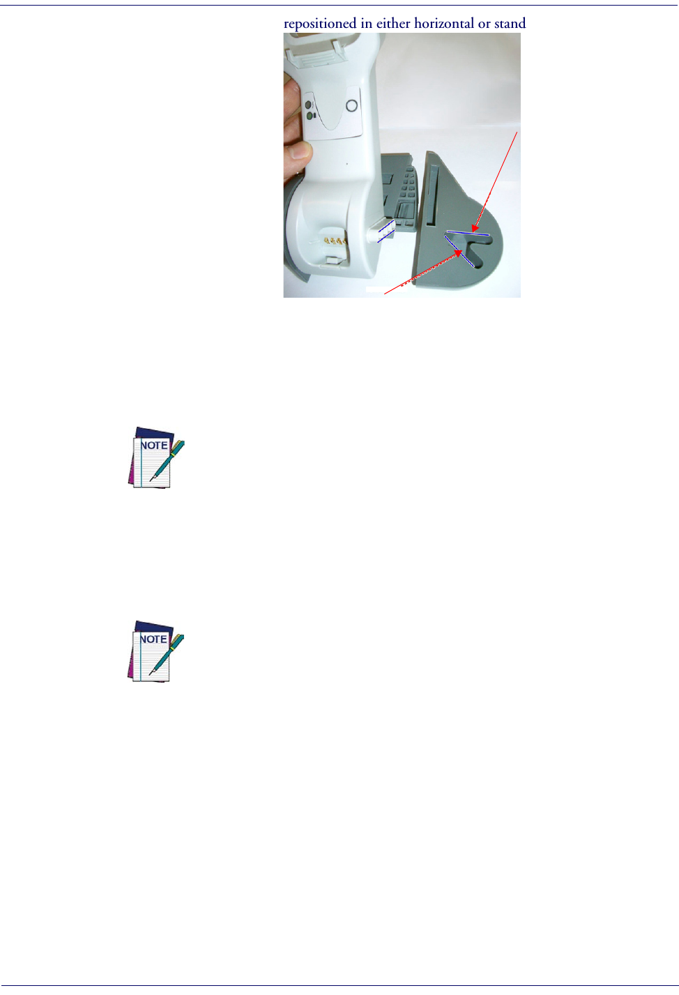
Setup Configuring the Base Station
22
Gryphon™ I GD44XX
/
GBT4400/GM440X
3. The stand can now be repositioned in either horizontal or standing position.
Horizontal
Standing
Connecting the Base Station
Figure 7
shows how to connect the Base Station to a terminal, PC or other host device. Turn off
the host before connection and consult the manual for that equipment (if necessary) before
proceeding. Connect the interface cable before applying power to the Base Station.
The Gryphon GBT4400 can be set up to require a PIN code when connecting to the
host. If you are connecting to a system that uses a custom security PIN, follow the
procedure in "Connecting the Base when Security Pin is Enabled" on page
25
. For
information on how to configure this feature, see
"BT Security Mode" starting on page
247
.
Base Station Connection and Routing:
Fully insert the Power Cable and Interface (I/F) Cable
connectors into their respective ports in the underside of the Base Station (see
Figure 7
). Then
connect to an AC Adapter, and plug the AC power cord into the (wall) outlet.
Gryphon Wireless can also be Powered by the Terminal. When powered by the Ter-
minal, the battery charger is automatically set as Slow charge.
For some specific interfaces or hosts or lengths of cable, the use of an external
power supply may be recommended for full recharging capability (see
"Technical
Specifications" on page 293
for more details).

Configuring the Base Station Setup
Product Reference Guide
23
Figure 7. Connecting the Base Station
Base
Station
I/F Cable
AC/DC
Adapter
DC Power
Cord
Wall plug
Connector
Securing the DC Power Cord (Optional)
The DC power cord for the adapter can be secured to the bottom of the base in order to
maximize the mechanical retention of the cable itself. The routing of the power cord can be
changed to accommodate the base station positioning: horizontal, stand or wall mounting. The
cables can be looped around to the front of the Base Station, or fed directly out the back of the
Base Station, as shown in
Figure 8 on page 23
.
Figure 8. Options for routing the DC cord
Please refer to the arrows depicted on the bottom of the base when placing the cables, detailed in
Figure 9
.

Setup Configuring the Base Station
24
Gryphon™ I GD44XX
/
GBT4400/GM440X
Figure 9. Arrows showing routing
Host Connection:
Verify before connection that the reader’s cable type is compatible with your
host equipment.
Most connections plug directly into the host device as shown in
Figure 10
. Keyboard Wedge
interface cables have a ‘Y’ connection where its female end mates with the male end of the cable
from the keyboard and the remaining end at the keyboard port on the terminal/PC.
Figure 10. Connecting to the Host
U
S
B
I
B
M
K
e
y
b
o
a
r
d
W
e
d
g
e
W
a
n
d
or...
or...
or...
Power Connection :
Plug the AC Adapter in to an approved AC wall socket with the cable
facing downwards (as shown in
Figure 7
) to prevent undue strain on the socket.
Disconnecting the Cable:
To detach the cable, insert a paper clip or similar object into the hole
on the base, as shown in
Figure 11
.
Figure 11. Disconnecting the Cable
Insert
Paper Clip

Configuring the Base Station Setup
Product Reference Guide
25
Connecting the Base when Security Pin is Enabled
When connecting the Base to a system that has a custom Security Pin enabled, follow the steps
below in the order shown:
1. Power down the host system.
2. Connect the appropriate interface cable into the Base as shown in
Figure 10
.
3. Place the reader in the Base.
4. Power up the host. The reader will link to the Base
5. When the host completely powers up, a new custom Security Pin Code may be sent to the
reader and Base, depending on host configuration. Contact Datalogic Technical Support
for more information.
If you want to change security settings or set up a PIN, see
"BT Security
Mode" starting on page 247
.
Linking the Reader to a Base Station
RF Devices
For RF devices, before configuring the interface it is necessary to link the handheld with the
base. To link the handheld and the base, press the trigger to wake it and place it on the base. If
the reader was previously linked to another base, you must first scan the Unlink action
command before re-linking to the new base.
Unlnk
Unlnk
BT Models only
Remember: The mandatory condition for establishing a new linking between a BT handheld
and a BT base is that the handheld is unlinked and they share the same security configuration. A
successful link is indicated by three ascending tones from the reader. A high-low-high-low tone
indicates the link attempt was unsuccessful. A single green LED flash after this tone indicates no
Base Station was discovered. Two green LED flashes after this tone indicates that more than one
Base Station was discovered and the reader did not link. Three LED flashes after this tone
indicate a security error.

Setup Configuring the Base Station
26
Gryphon™ I GD44XX
/
GBT4400/GM440X
Linking a BT Reader to a PC
The reader can optionally be linked to a Bluetooth-enabled PC with the serial port profile, in
either server mode or client mode.
Linking to a PC in Server Mode (BT Slave Mode)
To link a BT reader in server mode to a Bluetooth-enabled PC, follow these steps:
1. Install any drivers provided with the Bluetooth adapter.
2. Scan the bar code below to make the scanner visible to the host computer.
³LnkSv
Link to a PC in Server Mode
3. Use the host computer’s Bluetooth manager to “Discover new devices” and select "Data-
logic Scanner." If you receive an error message, it may be necessary to disable security on
the device.
4. Select “connect” on the PC to link the reader to the PC. Use an RS-232 terminal program
to see incoming data on the port designated by the computer's Bluetooth manager.
Linking to a PC in Client Mode (BT Master Mode)
The reader can optionally be linked in client mode to a Bluetooth-enabled PC with the serial
port profile. To do this, follow these steps:
1. Ensure the PC or terminal can network with Bluetooth devices and that it is powered on.
2. Ensure that a COM port is assigned under Services within the Bluetooth setup menu.
3. Create a Link label that contains the address of the PC Bluetooth adapter.
NOTE
The Bluetooth address can be found under "Properties" within in the
Bluetooth setup menu.
The link label is a Code 128 function 3 label with the following format:
<FN3 char>LnkB<12 character Bluetooth address>
4. Scan the link label you created in step 3.
Power Off
Shuts off power to the BT handheld until next trigger pull. This function only applies to the BT
model.

Gryphon™ 2D System and Network Layouts Setup
Product Reference Guide
27
Gryphon™ 2D System and Network Layouts
Stand Alone Layouts
Figure 12. Single Reader Layout
Figure 13. Multiple Reader Layout
Wireless models only
(not valid for BT model)
In stand alone systems, each base station is connected to a single Host.

Setup Gryphon™ 2D System and Network Layouts
28
Gryphon™ I GD44XX
/
GBT4400/GM440X
Figure 14. Multiple Stand Alone Layouts
Mobile models only
(not valid for BT model)
Many stand alone connections can operate in the same physical area without interference,
provided all readers and base stations in the system have different addresses.

Interface Selection Setup
Product Reference Guide
29
Interface Selection
Upon completing the physical connection between the reader and its host, proceed to Table 1
starting on page 30
to select the interface type the reader is connected to (for example: RS-232,
Keyboard Wedge, USB, etc.). Scan the appropriate bar code in that section to configure your
system’s correct interface type.
Each reader model will support one of the following sets of host interfaces:
General Purpose Models Retail Point of Sale Models
•RS-232
• RS-232 OPOS
•USB-COM
• Keyboard Wedge
• Wand Emulation (BT only)
•RS-232
• RS-232 OPOS
•USB
• IBM 46XX
Setting the Interface
Scan the programming bar code from this section which selects the appropriate interface type
matching the system the reader will be connected to. Next, proceed to the corresponding
section in this manual (also listed in
Table 1 on page 30
) to configure any desired settings and
features associated with that interface.
Unlike some programming features and options, interface selections
require that you scan only one programming bar code label. DO NOT
scan an ENTER/EXIT bar code prior to scanning an interface selection bar
code.
Some interfaces require the scanner to start in the disabled state when
powered up. If additional scanner configuration is desired while in this
state, pull the trigger and hold it for five seconds. The scanner will
change to a state that allows programming with bar codes.

Setup Interface Selection
30
Gryphon™ I GD44XX
/
GBT4400/GM440X
Table 1. Available Interfaces
RS-232 FEATURES
RS-232 standard interface
Select RS232-STD
Set RS-232
Interface
Features
starting on
page 41
$P,HA12,P(CR)
Select RS232-WN
RS-232 Wincor-Nixdorf
RS-232 for use with OPOS/UPOS/JavaPOS
$P,HA13,P(CR)
Select RS-232 OPOS
$P,HA47,P(CR)
Select USB-COM-STDa
a. Download the correct USB Com driver from www.datalogic.com
USB Com to simulate RS-232 standard interface
IBM FEATURES
$P,HA08,P(CR)
Select IBM-P5B
IBM-46xx Port 5B reader interface
Set IBM
Interface
Features
starting on
page 67
IBM-46xx Port 9B reader interface
$P,HA23,P(CR)
Select IBM-P9B
USB-OEM FEATURES
$P,HA45,P(CR)
Select USB-OEM
USB-OEM
(can be used for OPOS/UPOS/JavaPOS)
Set USB-OEM
Interface
Features
starting on
page 65

KEYBOARD FEATURES
$P,HA2B,P(CR)
Select USB Alternate Keyboard
USB Keyboard with alternate key encoding
AT, PS/2 25-286, 30-286, 50, 50Z, 60, 70,
80, 90 & 95 w/Standard Key Encoding
$P,HA29,P(CR)
Select KBD-AT
Set KEYBOARD
WEDGE
Interface
Features
starting on page
55
$P,HA11,P(CR)
Select KBD-AT-NK
Keyboard Wedge for IBM AT PS2 with
standard key encoding but without
external keyboard
AT, PS/2 25-286, 30-286, 50, 50Z, 60, 70,
80, 90 & 95 w/Alternate Key
$P,HA26,P(CR)
Select KBD-AT-ALT
$P,HA10,P(CR)
Select KBD-AT-ALT-NK
Keyboard Wedge for IBM AT PS2 with
alternate key encoding but without
external keyboard
PC/XT w/Standard Key Encoding
$P,HA28,P(CR)
Select KBD-XT
$P,HA14,P(CR)
Select KBD-IBM-3153
Keyboard Wedge for IBM Terminal 3153
Interface Selection Setup
Product Reference Guide
31

KEYBOARD — cont. FEATURES
Keyboard Wedge for IBM Terminals
31xx, 32xx, 34xx, 37xx make only key-
board
$P,HA15,P(CR)
Select KBD-IBM-M
Set KEYBOARD
WEDGE
Interface
Features
starting on page 55
$P,HA16,P(CR)
Select KBD-IBM-MB
Keyboard Wedge for IBM Terminals
31xx, 32xx, 34xx, 37xx make break key-
board
Keyboard Wedge for DIGITAL Termi-
nals VT2xx, VT3xx, VT4xx
$P,HA1B,P(CR)
Select KBD-DIG-VT
$P,HA35,P(CR)
Select USB Keyboard
USB Keyboard with standard key encoding
USB Keyboard for Apple computers
$P,HA2C,P(CR)
Select USB-KBD-APPLE
WAND EMULATION FEATURES
Wand Emulation
( B T o n l y )
$P,HA24,P(CR)
Select WAND
Set WAND
Interface
Features
starting on page 71
Setup Interface Selection
32
Gryphon™ I GD44XX
/
GBT4400/GM440X

Customizing Configuration Settings Setup
Product Reference Guide
33
Customizing Configuration Settings
Configure Interface Settings
If after scanning the interface bar code from the previous table, your installation requires you to
select options to further customize your reader, turn to the appropriate section for your interface
type in
"Configuration Parameters" starting on page 37
.
•
"RS-232 Interface" on page 41
•
"RS-232/USB-Com Interfaces" on page 46
•
"Keyboard Settings" on page 55
•
"RS-232/USB-Com Interfaces" on page 46
•
"IBM 46XX Interface" on page 67
•
"Wand Emulation Interface" on page 71
Global Interface Features
See "
Global Interface Features" on page 39
for settings configurable by all interface types.
Configuring Other Features
If your installation requires different programming than the standard factory default settings,
the following sections of this manual allow configuration of non-interface-specific settings you
might require:
Reading Parameters
:
Reading Parameters include programming for scanning, beeper and LED
indicators and other universal settings.
1D Symbologies
:
Includes options concerning the bar code label types (symbologies). These
settings allow you to enable/disable symbologies, set label lengths, require check digit, etc.
WIRELESS FEATURES
:
Contains programming options for RF, STAR and Bluetooth models only.
Software Version Transmission
The software version of the device can be transmitted over the RS-232 and Keyboard interfaces
by scanning the following label.
Transmit Software Version
RevA

Setup Customizing Configuration Settings
34
Gryphon™ I GD44XX
/
GBT4400/GM440X
Resetting the Product Configuration to Defaults
Restore Custom Defaults
If you aren’t sure what programming options are in your imager, or you’ve changed some
options and want to restore the Custom Default Configuration that may have been saved in the
scanner, scan the Restore Custom Default Configuration bar code below. This will restore the
custom configuration for the currently active interface.
Restore Custom Default Configuration
$P,HA00,P(CR)
Custom defaults are based on the interface type. Configure the imager
for the correct interface before scanning this label.
Restore Factory Configuration
If you want to restore the Factory Configuration for your imager, scan either the Restore USA
Factory Configuration bar code or the Restore EU Factory Configuration bar code below. Both
labels restore the scanner configuration to the factory settings, including the interface type. The
USA label restores Label IDs to those historically used in the USA. The EU label restores Label
IDs to those historically used in Europe. The Label ID sets for USA and EU are shown in the
“Label ID Control” section on page 81
of this manual.
$P,AE,P(CR)
Restore USA Factory Configuration
$P,Ae,P(CR)
Restore EU Factory Configuration
The programming items listed in the following sections show the factory default settings for
each of the menu commands.

Customizing Configuration Settings Setup
Product Reference Guide
35
Replacing the Battery
Before replacing the Battery, read
"Battery Safety" starting on page 14
. Datalogic recommends
annual replacement of rechargeable battery packs to ensure maximum performance.
To change the battery of your reader, complete the following instructions.
1. With a screwdriver, unscrew the battery cover screw.
2. Unscrew and remove the three screws securing the battery holder, and unplug the white
connector.
Connector
Screw Screw
3. Carefully lift out the gold contacts circuit, and remove the battery holder while letting the
white connector pass through the hole in the battery holder (as shown in the picture
below).
Pass-through
hole
Gold
contacts
circuit

Setup Customizing Configuration Settings
36
Gryphon™ I GD44XX
/
GBT4400/GM440X
4. Remove the old battery from its place (if present), and insert the new battery in the same
position.
5. Replace the battery holder and three screws, plug in the connector, and return the contacts
circuit to its previous location.
When inserting the new battery into the handle, take care to position the battery
and the connector as shown.
6. Insert the cover in the handle and screw it back into place.
Battery replacement is now complete.

Product Reference Guide
37
Chapter 3
Configuration Using Bar Codes
This and following sections provide programming bar codes to configure your reader by
changing the default settings. For details about additional methods of programming, see
"Configuration Methods" on page 16.
You must first enable your reader to read bar codes in order to use this
section. If you have not done this, go to
Setup, starting on page 17
and
complete the appropriate procedure.
Configuration Parameters
Once the reader is set up, you can change the default parameters to meet your application needs.
Refer to "Standard Defaults" starting on page 303 for initial configuration in order to set the
default values and select the interface for your application.
The following configuration parameters are divided into logical groups, making it easy to find
the desired function based on its reference group.
Interface Configuration:
•"RS-232/USB-Com Interfaces" on page 46
•"Keyboard Settings" on page 55
Parameters common to all interface applications:
•"Data Format" on page 75 gives options to control the messages sent to the Host system.
•"Reading Parameters" on page 89 control various operating modes and indicators status
functioning.
Symbology-specific parameters:
•"1D Symbologies" on page 111 provides configuration of a personalized mix of 1D codes,
code families and their options.
•"2D Symbologies" on page 203 provides configuration of a personalized mix of 2D codes,
code families and their options.
You must first enable your reader to read bar codes in order to use this
section. If you have not done this, go to
Setup, starting on page 17
and
complete the appropriate procedure.

Enter/Exit Programming Mode
38
Gryphon™ I GD44XX
/
GBT4400/GM440X
To program features:
1. Scan the ENTER/EXIT PROGRAMMING bar code, available at the top of each pro-
gramming page, when applicable.
2. Scan the bar code to set the desired programming feature. You may need to cover unused
bar codes on the page, and possibly the facing page, to ensure that the reader reads only
the bar code you intend to scan.
3. If additional input parameters are needed, go to Appendix D, Keypad, and scan the
appropriate characters from the keypad.
Additional information about many features can be found in the “Refer-
ences” chapter.
If you make a mistake before the last character, scan the CANCEL bar code
to abort and not save the entry string. You can then start again at the
beginning.
4. Complete the programming sequence by scanning the ENTER/EXIT PROGRAM-
MING bar code to exit Programming Mode.
For more detailed descriptions, programming information and examples for setting selected
configuration items, see References, starting on page 255.
By default, the handheld will decode bar code labels only when they are
close to the center of the aiming pattern. This allows the handheld to accu-
rately target labels when they are placed close together, such as on a pick
sheet. See
Pick Mode, starting on page 100.

Global Interface Features Enter/Exit Programming Mode
Product Reference Guide
39
GLOBAL INTERFACE FEATURES
The following interface features are configurable by all interface types.
Host Commands — Obey/Ignore
This option specifies whether the reader will obey or ignore host commands. When set to
ignore, the reader will ignore all host commands except for those necessary for:
•service mode
• flash programming mode
• keeping the interface active
• transmission of labels.
DEFAULT
$CIFIH00(CR)
Host Commands = Obey
(Do Not Ignore Host Commands)
$CIFIH01(CR)
Host Commands = Ignore
USB Suspend Mode
This setting enables/disables the ability of USB interfaces to enter suspend mode.
DEFAULT
$CUSSE00(CR)
USB Suspend Mode = Disable
$CUSSE01(CR)
USB Suspend Mode = Enable

Enter/Exit Programming Mode Global Interface Features
40
Gryphon™ I GD44XX
/
GBT4400/GM440X
NOTES

RS-232 INTERFACE
BAUD RATE on page 42
DATA BITS on page 43
STOP BITS on page 43
PARITY on page 44
HANDSHAKING CONTROL on page 45
Use the programming bar codes in this section if modifications to the standard RS-232 interface settings are
necessary to meet your system’s requirements. Additional settings which apply to both the RS-232 and USB
interfaces are available in the next section, "RS-232/USB-Com Interfaces" starting on page 46.
Reference Appendix B, Standard Defaults for a listing of standard factory settings.

Enter/Exit Programming Mode RS-232 Interface
42
Gryphon™ I GD44XX
/
GBT4400/GM440X
Baud Rate
See page 256 for information on this feature.
$CR2BA00(CR)
Baud Rate = 1200
$CR2BA01(CR)
Baud Rate = 2400
$CR2BA02(CR)
Baud Rate = 4800
$CR2BA03(CR)
Baud Rate = 9600
DEFAULT
$CR2BA04(CR)
Baud Rate = 19,200
$CR2BA05(CR)
Baud Rate = 38,400
$CR2BA06(CR)
Baud Rate = 57,600
$CR2BA07(CR)
Baud Rate = 115,200

RS-232 Interface Enter/Exit Programming Mode
Product Reference Guide
43
Data Bits
This parameter allows the reader to interface with devices requiring a 7-bit or 8-bit ASCII protocol for sending and
receiving data.
$CR2DA00(CR)
7 Data Bits
$CR2DA01(CR)
8 Data Bits
DEFAULT
Stop Bits
Set the number of stop bits to match host device requirements. See page 256 for more information on this feature.
DEFAULT
$CR2ST00(CR)
1 Stop Bit
$CR2ST01(CR)
2 Stop Bits
Enter/Exit Programming Mode RS-232 Interface
44
Gryphon™ I GD44XX
/
GBT4400/GM440X
Parity
This feature specifies parity required for sending and receiving data. Select the parity type according to host device
requirements. See page 256 for more information.
DEFAULT
$CR2PA00(CR)
Parity = None
$CR2PA01(CR)
Parity = Even
$CR2PA02(CR)
Parity = Odd

RS-232 Interface Enter/Exit Programming Mode
Product Reference Guide
45
Handshaking Control
DEFAULT
$CR2HC00(CR)
Handshaking Control = RTS
$CR2HC01(CR)
Handshaking Control = RTS/CTS
$CR2HC02(CR)
Handshaking Control = RTS/XON/XOFF
$CR2HC03(CR)
Handshaking Control = RTS On/CTS
$CR2HC04(CR)
Handshaking Control = RTS/CTS Scan Control
See page 256 for more information about this feature.

RS-232/USB-COM INTERFACES
INTERCHARACTER DELAY on page 47
BEEP ON ASCII BEL on page 47
BEEP ON NOT ON FILE on page 48
ACK NAK OPTIONS on page 49
ACK CHARACTER on page 50
NAK CHARACTER on page 50
ACK NAK TIMEOUT VALUE on page 51
ACK NAK RETRY COUNT on page 51
ACK NAK ERROR HANDLING on page 52
INDICATE TRANSMISSION FAILURE on page 52
DISABLE CHARACTER on page 53
ENABLE CHARACTER on page 53
The programming bar codes in this chapter allow modifications to the standard RS-232 and USB-Com interfaces.
Reference Appendix B, Standard Defaults for a listing of standard factory settings.

RS-232/USB-Com Interfaces Enter/Exit Programming Mode
Product Reference Guide
47
Intercharacter Delay
This parameter specifies the intercharacter delay between the end of one character and the beginning of the next.
The delay can be set within a range of zero (0) to 990 milliseconds in 10ms increments. A setting of zero specifies
no delay.
See page 265 for more information.
$CR2IC00(CR)
Intercharacter Delay = No Delay
$CR2IC
Select Intercharacter Delay Setting
To configure this feature, scan the ENTER/EXIT
PROGRAMMING MODE bar code above, then the
bar code at left followed by the digits from the
Alphanumeric characters in Appendix D, Keypad
representing your desired character(s). End by
scanning the ENTER/EXIT bar code again.
Make a mistake? Scan the CANCEL bar code to abort
and not save the entry string. You can then start again at
the beginning.
~
CANCEL
DEFAULT
00 = No Intercharacter Delay
Beep On ASCII BEL
When this parameter is enabled, the reader issues a beep when a <BEL> character is detected on the RS-232 serial
line. <BEL> is issued to gain a user's attention to an illegal entry or other important event.
$CR2BB00(CR)
Beep On ASCII BEL = Disable
DEFAULT
$CR2BB01(CR)
Beep On ASCII BEL = Enable
Enter/Exit Programming Mode RS-232/USB-Com Interfaces
48
Gryphon™ I GD44XX
/
GBT4400/GM440X
Beep On Not on File
This option enables/disables the action of the reader to sound a three beep sequence upon receiving a Not-On-File
(NOF) host command.
$CBPNF00(CR)
Beep On Not On File = Disable
DEFAULT
$CBPNF01(CR)
Beep On Not On File = Enable
RS-232/USB-Com Interfaces Enter/Exit Programming Mode
Product Reference Guide
49
ACK NAK Options
This enables/disables the ability of the reader to support the RS-232 ACK/NAK protocol.
See page 258 for more information.
DEFAULT
$CR2AE00(CR)
ACK/NAK Protocol = Disable ACK/NAK
$CR2AE01(CR)
ACK/NAK Protocol = Enable for label transmission
$CR2AE02(CR)
ACK/NAK Protocol = Enable for host-command
acknowledge
$CR2AE03(CR)
ACK/NAK Protocol = Enable for label transmission and
host-command acknowledge

Enter/Exit Programming Mode RS-232/USB-Com Interfaces
50
Gryphon™ I GD44XX
/
GBT4400/GM440X
ACK Character
This setting specifies an ASCII character or hex value to be used as the ACK character. ASCII characters or any hex
value from 0 to 0xFF can be selected. See page 258 for more information.
$CR2AC
Select ACK Character Setting
DEFAULT
0x06 ‘ACK’ Character
Setting to previously defined characters such as XON, XOFF, or host commands conflicts with normal
operation of these characters. 8-bit data is not recognized when the option
Data Bits
has been set as
7 Data Bits.
NAK Character
This setting specifies an ASCII character or hex value to be used as the NAK character. ASCII characters or any hex
value from 0 to 0xFF can be selected.
Setting to previously defined characters such as XON, XOFF, or host commands conflicts with normal
operation of these characters. 8-bit data is not recognized when the option
Data Bits
has been set as
7 Data Bits.
See page 259 for more information.
$CR2NA
Select NAK Character Setting
DEFAULT
0x15 ‘NAK’ Character
RS-232/USB-Com Interfaces Enter/Exit Programming Mode
Product Reference Guide
51
ACK NAK Timeout Value
This option specifies the amount of time the reader waits for an ACK character from the host following label
transmission. The selectable timeout range is 200 milliseconds to 15,000ms (15 seconds) in 200ms increments. A
selection of 0 disables the timeout.
See page 260 for more information on setting this feature.
$CR2AT
Select ACK NAK Timeout Value Setting
To configure this feature, scan the ENTER/EXIT
PROGRAMMING MODE bar code above, then the
bar code at left followed by the digits from the
Alphanumeric characters in Appendix D, Keypad
representing your desired character(s). End by
scanning the ENTER/EXIT bar code again.
Make a mistake? Scan the CANCEL bar code to abort and
not save the entry string. You can then start again at the
beginning.
~
CANCEL
DEFAULT
01 ACK NAK Timeout value is 200ms
ACK NAK Retry Count
This feature specifies the number of times the reader retries a label transmission due to a retry condition. The
selectable range is from 1 to 254 retries. A selection of 0 disables the count, and a selection of 255 specifies
unlimited retries. See page 261 for more information.
$CR2AR
Select ACK NAK Retry Count Setting
To configure this feature, scan the ENTER/EXIT
PROGRAMMING MODE bar code above, then the
bar code at left followed by the digits from the
Alphanumeric characters in Appendix D, Keypad
representing your desired character(s). End by
scanning the ENTER/EXIT bar code again.
Make a mistake? Scan the CANCEL bar code to abort and
not save the entry string. You can then start again at the
beginning.
~
CANCEL
DEFAULT
003 = 3 Retries

Enter/Exit Programming Mode RS-232/USB-Com Interfaces
52
Gryphon™ I GD44XX
/
GBT4400/GM440X
ACK NAK Error Handling
This feature specifies the method the reader uses to handle receive errors detected while waiting for an ACK
character from the host.
DEFAULT
$CR2EH00(CR)
ACK NAK Error Handling = Ignore Errors Detected
$CR2EH01(CR)
ACK NAK Error Handling = Process Error as Valid ACK
Character
$CR2EH02(CR)
ACK NAK Error Handling = Process Error as
Valid NAK Character
Indicate Transmission Failure
This option enables/disables the reader’s ability to sound an error beep to indicate a transmission failure while in
ACK/NAK mode
$CR2TF00(CR)
Indicate Transmission Failure = Disable Indication
$CR2TF01(CR)
Indicate Transmission Failure = Enable Indication
DEFAULT
.

RS-232/USB-Com Interfaces Enter/Exit Programming Mode
Product Reference Guide
53
Disable Character
Specifies the value of the RS-232 host command used to disable the reader.
ASCII characters or any hex value from 0 to 0xFF can be selected.
Setting to previously defined characters such as XON, XOFF, or host commands conflicts with
normal operation of these characters. 8-bit data is not recognized when the option
Data Bits
has been set as 7 Data Bits.
See page 262 for more information on setting this feature.
$CR2DC
Select Disable Character Setting
DEFAULT
0x44 = Disable Character is ‘D’
Enable Character
Specifies the value of the RS-232 host command used to enable the reader.
ASCII characters or any hex value from 0 to 0xFF can be selected.
Setting to previously defined characters such as XON, XOFF, or host commands conflicts with
normal operation of these characters. 8-bit data is not recognized when the option
Data Bits
has been set as 7 Data Bits.
See page 263 in “References” for more information on setting this feature.
$CR2EC
Select Enable Character Setting
DEFAULT
0x45 = Enable Character is ‘E’

Enter/Exit Programming Mode RS-232/USB-Com Interfaces
54
Gryphon™ I GD44XX
/
GBT4400/GM440X
NOTES

KEYBOARD SETTINGS
COUNTRY MODE on page 56
SEND CONTROL CHARACTERS on page 60
WEDGE QUIET INTERVAL on page 61
INTERCODE DELAY on page 61
CAPS LOCK STATE on page 62
NUMLOCK on page 62
USB KEYBOARD SPEED on page 63
USB KEYBOARD NUMERIC KEYPAD on page 64
Use the programming bar codes in this chapter to select options for USB Keyboard and Wedge Interfaces.
Reference Appendix B, Standard Defaults for a listing of standard factory settings.
Information about control character emulation which applies to keyboard interfaces is listed in Appendix E,
Scancode Tables.

Enter/Exit Programming Mode Keyboard Settings
56
Gryphon™ I GD44XX
/
GBT4400/GM440X
Country Mode
This feature specifies the country/language supported by the keyboard. Several languages are supported:
DEFAULT
$CKBCO00(CR)
Country Mode = U.S.
$CKBCO01(CR)
Country Mode = Belgium
$CKBCO02(CR)
Country Mode = Britain
$CKBCO11(CR)
Country Mode = Croatia
Supports only the interfaces listed in the Country
Mode feature description.
Supports only the interfaces listed in the Country
Mode feature description.
$CKBCO0E(CR)
Country Mode = Czech Republic
$CKBCO03(CR)
Country Mode = Denmark
Supports only the interfaces listed in the Country
Mode feature description.

Keyboard Settings Enter/Exit Programming Mode
Product Reference Guide
57
Country Mode (Continued)
$CKBCO04(CR)
Country Mode = France
Supports only the interfaces listed in the Country
Mode feature description.
$CKBCO13(CR)
Country Mode = French Canadian
$CKBCO05(CR)
Country Mode = Germany
Supports only the interfaces listed in the Country
Mode feature description.
$CKBCO0D(CR)
Country Mode = Hungary
$CKBCO06(CR)
Country Mode = Italy
Supports only the interfaces listed in the Country
Mode feature description.
$CKBCO0C(CR)
Country Mode = Japanese 106-key
Enter/Exit Programming Mode Keyboard Settings
58
Gryphon™ I GD44XX
/
GBT4400/GM440X
Country Mode (Continued)
$CKBCO14(CR)
Country Mode = Lithuanian
Supports only the interfaces listed in the Country
Mode feature description.
$CKBCO07(CR)
Country Mode = Norway
$CKBCO12(CR)
Country Mode = Poland
Supports only the interfaces listed in the Country
Mode feature description.
Supports only the interfaces listed in the Country
Mode feature description.
$CKBCO08(CR)
Country Mode = Portugal
$CKBCO10(CR)
Country Mode = Romania
Supports only the interfaces listed in the Country
Mode feature description.
Supports only the interfaces listed in the Country
Mode feature description.
$CKBCO0F(CR)
Country Mode = Slovakia

$CKBCO09(CR)
Keyboard Settings Enter/Exit Programming Mode
Product Reference Guide
59
Country Mode = Spain
$KBCO0A(CR)
Country Mode = Sweden
$CKBCO0B(CR)
Country Mode = Switzerland
Supports only the interfaces listed in the Country
Mode feature description.

Enter/Exit Programming Mode Keyboard Settings
60
Gryphon™ I GD44XX
/
GBT4400/GM440X
Send Control Characters
This feature specifies how the reader transmits ASCII control characters to the host. Reference Appendix E,
Scancode Tables for more information about control characters.
Options are as follows:
Control Character 00 :
Characters from 00 to 0x1F are sent as control character Ctrl+Keys, special keys are located
from 0x80 to 0xA1.
Control Character 01 :
Characters from 00 to 0x1F are sent as control character Ctrl+Shift, special keys are located
from 0x80 to 0xA1.
Control Character 02 :
Special keys are located from 00 to 0x1F and characters from 0x80 to 0xFE are intended as
an extended ASCII table (see "Microsoft Windows Codepage 1252" on page 329).
DEFAULT
$CKBSC00(CR)
Wedge Send Control Characters = 00
$CKBSC01(CR)
Wedge Send Control Characters = 01
$CKBSC02(CR)
Wedge Send Control Characters = 02

Keyboard Settings Enter/Exit Programming Mode
Product Reference Guide
61
Wedge Quiet Interval
Specifies amount of time to look for keyboard activity before scanner breaks keyboard connection in order to
transmit data to host. The selectable range for this setting is 00 to 990 milliseconds (00-0x63 by 01) in increments
of ten milliseconds. See page 264 in “References” for detailed information and examples for setting this feature.
$CKBQI
Set Wedge Quiet Interval
To configure this feature, scan the ENTER/EXIT
PROGRAMMING MODE bar code above, then the
bar code at left followed by the digits from the
Alphanumeric characters in Appendix D, Keypad
representing your desired character(s). End by
scanning the ENTER/EXIT bar code again.
Make a mistake? Scan the CANCEL bar code to
abort and not save the entry string. You can then
start again at the beginning.
~
CANCEL
DEFAULT
0A = Quiet Interval is
100 milliseconds
Intercode Delay
Specifies the delay between labels transmitted to the host for this interface. The selectable range for this feature is
from 0 to 99 seconds.
See page 266 in “References” for detailed information and examples for setting this feature.
$CKBID
Set Intercode Delay
To configure this feature, scan the ENTER/EXIT
PROGRAMMING MODE bar code above, then the
bar code at left followed by the digits from the
Alphanumeric characters in Appendix D, Keypad
representing your desired character(s). End by
scanning the ENTER/EXIT bar code again.
Make a mistake? Scan the CANCEL bar code to
abort and not save the entry string. You can then
start again at the beginning.
~
CANCEL
DEFAULT
00 = No Wedge Intercode Delay

Enter/Exit Programming Mode Keyboard Settings
62
Gryphon™ I GD44XX
/
GBT4400/GM440X
Caps Lock State
This option specifies the format in which the reader sends character data. This does not apply when an alternate
key encoding keyboard is selected.
DEFAULT
$CKBCL00(CR)
Caps Lock State = Caps Lock OFF
$CKBCL01(CR)
Caps Lock State = Caps Lock ON
$CKBCL02(CR)
Caps Lock State = AUTO Caps Lock Enable
Numlock
This option specifies the setting of the NUMLOCK key in the Keyboard Wedge interface.
DEFAULT
$CKBNL00(CR)
Numlock = NUMLOCK key unchanged
$CKBNL01(CR)
Numlock = Numlock key toggled

Keyboard Settings Enter/Exit Programming Mode
Product Reference Guide
63
USB Keyboard Speed
This option specifies the USB poll rate for a USB keyboard.
DEFAULT
$CKBSP01(CR)
USB Keyboard Speed = 1ms
$CKBSP02(CR)
USB Keyboard Speed = 2ms
$CKBSP03(CR)
USB Keyboard Speed = 3ms
$CKBSP04(CR)
USB Keyboard Speed = 4ms
$CKBSP05(CR)
USB Keyboard Speed = 5ms
$CKBSP06(CR)
USB Keyboard Speed = 6ms
This feature applies ONLY to the USB Keyboard interface.

$CKBSP07(CR)
USB Keyboard Speed = 7ms
$CKBSP08(CR)
USB Keyboard Speed = 8ms
$CKBSP09(CR)
USB Keyboard Speed = 9ms
$CKBSP0A(CR)
USB Keyboard Speed = 10ms
Enter/Exit Programming Mode Keyboard Settings
64
Gryphon™ I GD44XX
/
GBT4400/GM440X
USB Keyboard Speed — continued
USB Keyboard Numeric Keypad
This option Controls whether numeric characters will be sent using standard keys or the numeric keypad.
DEFAULT
$CKBKP00(CR)
Standard Keys
$CKBKP01(CR)
Numeric Keypad

USB-OEM INTERFACE
USB-OEM DEVICE USAGE on page 66
INTERFACE OPTIONS on page 66
Feature settings for USB interfaces differ depending upon which host type the reader will be connected with.
Use the feature settings in this chapter and "IBM 46XX Interface" on page 67 to specifically configure for the
USB-OEM interface. Other USB interfaces are included in the appropriate chapter for their host type.
Reference Appendix B for a listing of standard factory settings.

Enter/Exit Programming Mode USB-OEM Interface
66
Gryphon™ I GD44XX
/
GBT4400/GM440X
USB-OEM Device Usage
The USB-OEM protocol allows for the reader to be identified as one of two different types of bar code scanners.
Depending on what other scanners you may already have connected to a USB-OEM POS, you may need to change
this setting to enable all devices to communicate.
Options are:
• Table Top Scanner
• Handheld Scanner
$CIBUT00(CR)
USB-OEM Device Usage = Table Top Scanner
$CIBUT01(CR)
USB-OEM Device Usage = Handheld Scanner
DEFAULT
It may be necessary to switch device usage when connecting two readers/scanners of the same
type to a POS system.
Interface Options
$CIFO101(CR)
Obey Scanner Configuration Host Commands
$CIFO102(CR)
Ignore Scanner Configuration Host Commands
DEFAULT
This feature provides for an interface-specific control mechanism.

Enter/Exit Programming Mode IBM 46XX Interface
68
Gryphon™ I GD44XX
/
GBT4400/GM440X
46xx Number of Host Resets
Specifies how many consecutive resets are processed before the reader starts a five-second period
to allow the user to enter Programming Mode and configure the reader. The configurable range
for this feature is 1 to 15 resets.
$CIBHR01(CR)
46xx Number of Host Resets = 1
$CIBHR02(CR)
46xx Number of Host Resets = 2
$CIBHR03(CR)
46xx Number of Host Resets = 3
$CIBHR04(CR)
46xx Number of Host Resets = 4
$CIBHR05(CR)
46xx Number of Host Resets = 5
$CIBHR06(CR)
46xx Number of Host Resets = 6
DEFAULT
$CIBHR07(CR)
46xx Number of Host Resets = 7

IBM 46XX Interface Enter/Exit Programming Mode
Product Reference Guide
69
46xx Number of Host Resets — cont.
$CIBHR08(CR)
46xx Number of Host Resets = 8
$CIBHR09(CR)
46xx Number of Host Resets = 9
$CIBHR0A(CR)
46xx Number of Host Resets = 10
$CIBHR0B(CR)
46xx Number of Host Resets = 11
$CIBHR0C(CR)
46xx Number of Host Resets = 12
$CIBHR0D(CR)
46xx Number of Host Resets = 13
$CIBHR0E(CR)
46xx Number of Host Resets = 14
$CIBHR0F(CR)
46xx Number of Host Resets = 15

Enter/Exit Programming Mode IBM 46XX Interface
70
Gryphon™ I GD44XX
/
GBT4400/GM440X
Transmit Labels in Code 39 Format
This feature enable/disables translation to Code 39 before transmitting label data to an IBM-
46XX or a USB-OEM host. Only the symbology identifier is modified for the translation. The
data is not converted to Code 39 or verified to be valid for Code 39.
Options are:
IBM Standard Format:
Send labels in standard IBM format.
Code 39 Format:
Translate the following symbologies to Code 39:
• USB-OEM: Code128, Code 93, and Codabar
• IBM-Port 5B: Code 128, Code 93, and Codabar
• IBM-Port 9B: Code 93 and Codabar
DEFAULT
$CIBC300(CR)
Transmit Labels in Code 39 Format =
IBM Standard Format
$CIBC301(CR)
Transmit Labels in Code 39 Format = Code 39 Format
Interface Options
$CIFO101(CR)
Obey Scanner Configuration Host Commands
$CIFO102(CR)
Ignore Scanner Configuration Host Commands
DEFAULT
This feature provides for an interface-specific control mechanism.
Enter/Exit Programming Mode Wand Emulation Interface
72
Gryphon™ I GD44XX
/
GBT4400/GM440X
Wand Signal Speed
This feature specifies the speed of the Wand output signal per nominal bar or space. Choices
are:
• 330 microseconds
• 660 microseconds
$CWASP00(CR)
Wand Signal Speed = 330ms
$CWASP01(CR)
Wand Signal Speed = 660ms
DEFAULT
Wand Polarity
This option specifies the polarity of the Wand output signal. Choices are:
• Quiet zones and spaces are high, bars are low
• Quiet zones and spaces are low, bars are high
$CWAPO00(CR)
Wand Polarity = Quiet Zones & Spaces High, Bars Low
$CWAPO01(CR)
Wand Polarity = Quiet Zones & Spaces Low, Bars High
DEFAULT
TTL logic levels:
0V <= Low <= 0.7V
2.4V <= High <= 5.25V

Wand Emulation Interface Enter/Exit Programming Mode
Product Reference Guide
73
Wand Idle State
This feature specifies the level of the Wand output signal when the reader is idle.
$CWAID00(CR)
Wand Idle State = Low
$CWAID01(CR)
Wand Idle State = High
DEFAULT
TTL logic levels:
0V <= Low <= 0.7V
2.4V <= High <= 5.25V
Transmit Noise
This option specifies the leading/trailing noise for the Wand interface.
DEFAULT
$CWATN00(CR)
Transmit Noise = Disable
$CWATN01(CR)
Transmit Noise = Transmit leading noise
$CWATN02(CR)
Transmit Noise = Transmit trailing noise
$CWATN03(CR)
Transmit Noise = Transmit leading and trailing noise
Enter/Exit Programming Mode Wand Emulation Interface
74
Gryphon™ I GD44XX
/
GBT4400/GM440X
Label Symbology Conversion
When this feature is enabled for the Wand Emulation interface, all bar code labels are converted
to a single symbology.
Options are:
• No conversion
• Convert to Code 39 symbology
• Convert to Code 39 Full ASCII
• Convert to Code 128 symbology
DEFAULT
$CWASC00(CR)
Label Symbology Conversion = No conversion
$CWASC01(CR)
Label Symbology Conversion = Convert to Code 39
$CWASC03(CR)
Label Symbology Conversion =
Convert to Code 39 Full ASCII
$CWASC02(CR)
Label Symbology Conversion = Convert to Code 128

Product Reference Guide
75
DATA FORMAT
GLOBAL PREFIX/SUFFIX starting on page 76
GLOBAL AIM ID starting on page 77
LABEL ID starting on page 80
•Label ID: Pre-Loaded Sets
•Individually Set Label ID
•Label ID Control
•Label ID Symbology Selection • 1D Symbologies
•Label ID Symbology Selection • 2D Symbologies
CASE CONVERSION starting on page 87
CHARACTER CONVERSION starting on page 88
CAUTION
It is not recommended to use these features with IBM interfaces.
The features in this chapter can be used to build specific user-defined data into a message
string. See “References” starting on page 268 for more detailed instructions on setting these
features.

Enter/Exit Programming Mode Global Prefix/Suffix
76
Gryphon™ I GD44XX
/
GBT4400/GM440X
Global Prefix/Suffix
This option sets up to 20 characters each from the set of ASCII characters or any hex value from
00 to FF. The characters may be added as a prefix (in a position before the bar code data, also
called a header) and/or as a suffix (in a position following the bar code data, also called a footer).
See page 269 for more detailed instructions on setting this feature.
To configure this feature, scan the ENTER/EXIT PROGRAMMING MODE bar code above
to place the unit in Programming Mode, then the “Set Global Prefix” or “Set Global Suffix,”
bar code followed by the digits (in hex) from the Alphanumeric characters in Appendix D,
Keypad representing your desired character(s). If less than the expected string of 20 characters
are selected, scan the ENTER/EXIT bar code to terminate the string. Exit programming mode
by scanning the ENTER/EXIT bar code again.
$CLFPR
Set Global Prefix
$CLFSU
Set Global Suffix
Make a mistake? Scan the CANCEL bar code to abort and not
save the entry string. You can then start again at the begin-
ning.
~
CANCEL
DEFAULT
No Global Prefix
Global Suffix = 0x0D (CR)

Global AIM ID Enter/Exit Programming Mode
Product Reference Guide
77
Global AIM ID
This feature enables/disables addition of AIM IDs for all symbology
types.
AIM label identifiers (as opposed to custom characters you select yourself as with label
identifiers) can be included with scanned bar code data. See Table 2 on page 3-77 for a listing of
AIM IDs.
AIM label identifiers consist of three characters as follows:
• A close brace character (ASCII ‘]’), followed by...
• A code character (see some samples in the table below), followed by...
• A modifier character (the modifier character is symbol dependent).
DEFAULT
$CAIEN00(CR)
Global AIM ID = Disable
$CAIEN01(CR)
Global AIM ID = Enable
Table 2
. AIM IDs
Tag Name
AIM ID code
character
AIM ID code
ASCII value
ABC CODABAR X 58
ANKER PLESSEY N 4E
AZTEC z 7A
CHINA SENSIBLE CODE X 58
CODABAR F 46
CODE11 H 48
CODE128 C 43
CODE32 A 41
CODE39 A 41
CODE39 CIP X 58
CODE39 DANISH PPT X 58
CODE39 LAPOSTE X 58
CODE39 PZN X 58
CODE93 G 47
DATABAR 14 e 65
DATABAR 14 COMPOSITE e 65
DATABAR EXPANDED e 65

Enter/Exit Programming Mode Global AIM ID
78
Gryphon™ I GD44XX
/
GBT4400/GM440X
DATABAR EXPANDED
COMPOSITE e 65
DATABAR LIMITED e 65
DATABAR LIMITED COMPOSITE e 65
DATA MATRIX d 64
EAN128 C 43
EAN128 COMPOSITE C 43
EAN13 E 45
EAN13 P2 E 45
EAN13 P5 E 45
EAN13 COMPOSITE E 45
EAN8 E 45
EAN8 P2 E 45
EAN8 P5 E 45
EAN8 COMPOSITE E 45
FOLLET 2OF5 X 58
I2OF5 I 49
IATA INDUSTRIAL 2OF5 X 58
INDUSTRIAL 2OF5 X 58
ISBN X 58
ISBT128 CONCAT X 58
ISSN X 58
MAXICODE U 55
MICRO QR Q 51
MICRO PDF L 4C
MSI M 4D
PDF417 L 4C
PLESSEY P 50
POSTAL AUSTRALIAN X 58
POSTAL IMB X 58
POSTAL JAPANESE X 58
POSTAL KIX X 58
POSTAL PLANET X 58
POSTAL PORTUGAL X 58
POSTAL POSTNET BB X 58
POSTAL ROYAL MAIL X 58
POSTAL SWEDISH X 58
POSTNET X 58
QR CODE Q 51
S25 S 53
TRIOPTIC X 58
UPCA E 45
UPCA P2 E 45
UPCA P5 E 45
UPCA COMPOSITE E 45
UPCE E 45
UPCE P2 E 45
UPCE P5 E 45
UPCE COMPOSITE E 45

Global AIM ID Enter/Exit Programming Mode
Product Reference Guide
79
Set AIM ID Individually for GS1-128
This feature configures a Label ID individually for the GS1-128 symbology and the
programming for this works the same way as Label ID. See Label ID: Set Individually Per
Symbology, starting on page 274 for detailed instructions on setting this feature.
$CU8AI00(CR)
Set AIM ID Individually for GS1-128 = Disable
$CU8AI01(CR)
Set AIM ID Individually for GS1-128 = Enable
DEFAULT

Enter/Exit Programming Mode Label ID
80
Gryphon™ I GD44XX
/
GBT4400/GM440X
Label ID
A Label ID is a customizable code of up to three ASCII characters (convert to Hex using the
ASCII Chart on the inside back cover of this manual), used to identify a bar code symbology
type. It can be appended previous to or following the transmitted bar code data depending upon
how this option is enabled. This feature provides options for configuring custom Label IDs or
individually per symbology (see "Individually Set Label ID" on page 81). If you wish to
program the reader to always include an industry standard label identifier for ALL symbology
types, see the previous feature "Global AIM ID" on page 77.
See Label ID, starting on page 271 of “References” for more information on setting this feature.
Label ID: Pre-Loaded Sets
The reader supports two pre-loaded sets of Label IDs. See Label ID: Pre-loaded Sets, starting on
page 271 for details on the USA set and EU set.
CAUTION
$AE(CR)
Label ID Pre-loaded Set = USA Set
$Ae(CR)
Label ID Pre-loaded Set = EU Set
DEFAULT
When changing from one Label ID set to another, all other reader
configuration settings, including the host interface type, will be
erased and set to the standard factory defaults. Any custom config-
uration or custom defaults will be lost.

Label ID Enter/Exit Programming Mode
Product Reference Guide
81
Individually Set Label ID
This feature configures a Label ID individually for a single symbology. To set, first define
whether you want it as a prefix or suffix by scanning a label below. Then turn to Label ID
Symbology Selection • 1D Symbologies, starting on page 82 to select the symbology you want
to set, followed by up to 3 characters from the ASCII Chart at the back of this manual. See
"Label ID: Set Individually Per Symbology" on page 274 for detailed instructions on setting this
feature.
Label ID Control
This option controls whether a Label ID is disabled, or sent as a prefix or suffix for a given
symbology type.
DEFAULT
$CIDCO00(CR)
Label ID Transmission = Disable
$CIDCO01(CR)
Label ID Transmission = Enable as Prefix
$CIDCO02(CR)
Label ID Transmission = Enable as Suffix

Enter/Exit Programming Mode Label ID
82
Gryphon™ I GD44XX
/
GBT4400/GM440X
Label ID Symbology Selection − 1D Symbologies
This option selects the symbology for which a Label ID is to be configured. See "Label ID" on
page 80 or page 274 in “References” for more detailed instructions.
$CACID
If less than the expected string of 3 characters are selected, scan the ENTER/
EXIT bar code twice to accept the selection and exit Programming Mode.
Set ABC Codabar Label ID Character(s)
$CP3ID
Set Code 32 Pharmacode Label ID Character(s)
$CALID
Set Anker Plessey Label ID Character(s)
$CC9ID
Set Code 93 Label ID Character(s)
$CPAID
Set Australian Postal Code Label ID Character(s)
$CI8ID
Set Concatenated ISBT 128 Label ID Character(s)
$CCBID
Set Codabar Label ID Character(s)
$CDPID
Set Danish PPT Label ID Character(s)
$CC1ID
Set Code 11 Label ID Character(s)
$C3BID
Set EAN 13 Label ID Character(s)
$CC8ID
Set Code 128 Label ID Character(s)
$C3MID
Set EAN 13 Composite Label ID Character(s)
$CC3ID
Set Code 39 Label ID Character(s)
$C32ID
Set EAN 13 P2 Label ID Character(s)

Label ID Enter/Exit Programming Mode
Product Reference Guide
83
Label ID Symbology Selection − 1D Symbologies (continued)
$CCCID
Set Code 39 CIP Label ID Character(s)
$C35ID
Set EAN 13 P5 Label ID Character(s)
$C8BID
Set EAN 8 Label ID Character(s)
$CXCID
Set GS1 DataBar Expanded Composite
Label ID Character(s)
$C8MID
Set EAN 8 Composite Label ID Character(s)
$CU8ID
Set GS1-128 Label ID Character(s)
$C82ID
Set EAN 8 P2 Label ID Character(s)
$CUMID
Set GS1-128 Composite Label ID Character(s)
$C85ID
Set EAN 8 P5 Label ID Character(s)
$CLBID
Set GSI DataBar Limited Label ID Character(s)
$CF2ID
Set Follett 2 of 5 Label ID Character(s)
$CLCID
GSI DataBar Limited Composite Label ID Character(s)
$C4BID
Set GS1 DataBar 14 Label ID Character(s)
$CG2ID
Set GTIN 2 Label ID Character(s)
$C4CID
Set GS1 DataBar 14 Composite Label ID Character(s)
$CG5ID
Set GTIN 5 Label ID Character(s)

Enter/Exit Programming Mode Label ID
84
Gryphon™ I GD44XX
/
GBT4400/GM440X
Label ID Symbology Selection − 1D Symbologies (continued)
$CXBID
Set GS1 DataBar Expanded Label ID Character(s)
$CGBID
Set GTIN 8 Label ID Character(s)
$CIAID
Set IATA Industrial 2 of 5 Label ID Character(s)
$CLPID
Set LaPoste Code 39 Label ID Character(s)
$CPMID
Set IMB Postal Code Label ID Character(s)
$CMSID
Set MSI Label ID Character(s)
$CU2ID
Set Industrial 2 of 5 Label ID Character(s)
$CPPID
Set Planet Postal Code Label ID Character(s)
$CI2ID
Set Interleaved 2 of 5 Label ID Character(s)
$CPLID
Set Plessey Label ID Character(s)
$CISID
Set ISBN Label ID Character(s)
$CPGID
Set Portugal Postal Code Label ID Character(s)
$CINID
Set ISSN Label ID Character(s)
$CPNID
Set Postnet Label ID Character(s)
$CPJID
Set Japan Postal Code Label ID Character(s)
$CPKID
Set Kix Postal Code Label ID Character(s)

Label ID Enter/Exit Programming Mode
Product Reference Guide
85
Label ID Symbology Selection − 1D Symbologies (continued)
$CPZID
Set PZN Code Label ID Character(s)
$CPBID
Set Postnet BB Label ID Character(s)
$CPRID
Set Royal Postal Code Label ID Character(s)
$CAMID
Set UPC-A Composite Label ID Character(s)
$CS2ID
Set Standard 2 of 5 Label ID Character(s)
$CA2ID
Set UPC-A P2 Label ID Character(s)
$CPSID
Set Swedish Postal Code Label ID Character(s)
$CA5ID
Set UPC-A P5 Label ID Character(s)
$CCTID
Set Trioptic Code Label ID Character(s)
$CEBID
Set UPC-E Label ID Character(s)
$CABID
Set UPC-A Label ID Character(s)
$CE5ID
Set UPC-E P5 Label ID Character(s)
$CAZID
Set Aztec Label ID Character(s)
$CMXID
Set Maxicode Label ID Character(s)
$CCSID
Set China Sensible Label ID Character(s)
$CP4ID
Set PDF 417 Label ID Character(s)
$CDMID
Set Data Matrix Label ID Character(s)
$CMIID
Set Micro PDF 417 Label ID Character(s)
$CMQID
Set Micro QR Label ID Character(s)
$CQRID
Set QR Code Label ID Character(s)
Enter/Exit Programming Mode Label ID
86
Gryphon™ I GD44XX
/
GBT4400/GM440X
Label ID Symbology Selection − 2D Symbologies

Label ID Enter/Exit Programming Mode
Product Reference Guide
87
Advanced Formatting: User Label Edit
Advanced formatting is available to create user label edit scripts. See the Datalogic Aladdin
configuration application or contact Technical Support.
Case Conversion
This feature allows conversion of the case of all alphabetic characters to upper or lower case.
DEFAULT
$CLFCA00(CR)
Case Conversion = Disable (no case conversion)
$CLFCA01(CR)
Case Conversion = Convert to upper case
$CLFCA02(CR)
Case Conversion = Convert to lower case
Case conversion affects ONLY scanned bar code data, and does not affect Label
ID, Prefix, Suffix, or other appended data.

Enter/Exit Programming Mode Label ID
88
Gryphon™ I GD44XX
/
GBT4400/GM440X
Character Conversion
Character conversion is an eight byte configuration item. The eight bytes are 4 character pairs
represented in hexadecimal ASCII values. The first character in the pair is the character that will
be converted. The second character in the pair is the character to convert to. If the character to
convert in a pair is FF, then no conversion is done.
$CLFCH
Configure Character Conversion
DEFAULT
0xFFFFFFFFFFFFFFFF
(No character conversion)
If less than the expected string of 16 characters are selected, scan the ENTER/
EXIT bar code twice to accept the selections and exit Programming Mode.

Product Reference Guide
89
READING PARAMETERS
DOUBLE READ TIMEOUT starting on page 90
LED AND BEEPER INDICATORS starting on page 92
•Power On Alert
•Good Read: When to Indicate
•Good Read Beep Type
•Good Read Beep Frequency
•Good Read Beep Length
•Good Read Beep Volume
•Good Read LED Duration
SCANNING FEATURES starting on page 97
•Scan Mode
•Stand Mode Indication
•Stand Operation
•Pick Mode
•Stand Mode Sensitivity
•Stand Mode Illumination Off Time
•Scanning Active Time
•Stand Illumination Control
•Flash On Time
•Flash Off Time
•Aiming Pointer
•Aiming Duration Timer
•Green Spot Duration
•Mobile Phone Mode
•Partial Label Reading Control
•Decode Negative Image
•Image Capture
CORDED ONLY FEATURES starting on page 107
•Corded Stand Mode
•Corded Stand Beep
MULTIPLE LABEL READING starting on page 109
•Multiple Labels per Frame
•Multiple Labels Ordering by Code Symbology
•Multiple Labels Ordering by Code Length

Reading Parameters Enter/Exit Programming Mode
Product Reference Guide
91
Double Read Timeout — continued
$CSNDR50(CR)
Double Read Timeout = 0.8 Second
$CSNDR5A(CR)
Double Read Timeout = 0.9 Second
$CSNDR64(CR)
Double Read Timeout = 1 Second

Enter/Exit Programming Mode Reading Parameters
92
Gryphon™ I GD44XX
/
GBT4400/GM440X
LED AND BEEPER INDICATORS
Power On Alert
Disables or enables the indication (from the Beeper) that the reader is receiving power.
$CBPPU00(CR)
Power On Alert = Disable (No Audible Indication)
$CBPPU01(CR)
Power On Alert = Power-up Beep
DEFAULT
Good Read: When to Indicate
This feature specifies when the reader will provide indication (beep and/or flash its green LED)
upon successfully reading a bar code.
DEFAULT
$CBPIN00(CR)
Indicate Good Read = After Decode
$CBPIN01(CR)
Indicate Good Read = After Transmit
$CBPIN02(CR)
Indicate Good Read =
After CTS goes inactive then active
Reading Parameters Enter/Exit Programming Mode
Product Reference Guide
93
Good Read Beep Type
Specifies whether the good read beep has a mono or bitonal beep sound.
DEFAULT
$CBPTY00(CR)
Good Read Beep Type = Mono
$CBPTY01(CR)
Good Read Beep Type = Bitonal
Good Read Beep Frequency
Adjusts the good read beep to sound at a selectable low, medium or high frequency, selectable
from the list below. (Controls the beeper’s pitch/tone.)
$CBPFR00(CR)
Good Read Beep Frequency = Low
$CBPFR01(CR)
Good Read Beep Frequency = Medium
DEFAULT
$CBPFR02(CR)
Good Read Beep Frequency = High
Reading Parameters Enter/Exit Programming Mode
Product Reference Guide
95
Good Read Beep Volume
Selects the beeper volume (loudness) upon a good read beep. There are three selectable volume
levels.
$CBPVO00CR)
Good Read Beep Volume = Beeper Off
$CBPVO01CR)
Good Read Beep Volume = Low
$CBPVO02CR)
Good Read Beep Volume = Medium
$CBPVO03CR)
Good Read Beep Volume = High
DEFAULT

Enter/Exit Programming Mode Reading Parameters
96
Gryphon™ I GD44XX
/
GBT4400/GM440X
Good Read LED Duration
This feature specifies the amount of time that the Good Read LED remains on following a good
read. The good read LED on time can be set within a range of 100 milliseconds to 25,500
milliseconds (0.1 to 25.5 seconds) in 100ms increments. A setting of 00 keeps the LED on until
the next trigger pull.
See page 277 in “References” for detailed instructions and examples for setting this feature.
$CLAGL00(CR)
Good Read LED Duration Setting =
Keep LED on until next trigger pull
$CLAGL
Select Good Read LED Duration Setting
To configure this feature, scan the ENTER/EXIT PRO-
GRAMMING MODE bar code above, then the bar code
at left followed by the digits from the Alphanumeric
characters in Appendix D, Keypad representing your
desired character(s). End by scanning the ENTER/EXIT
bar code again.
Make a mistake? Scan the CANCEL bar code to abort
and not save the entry string. You can then start again at
the beginning.
~
CANCEL
DEFAULT
003 = Good Read LED
stays on for 300 ms.
Indicators are dimmed during sleep.
Reading Parameters Enter/Exit Programming Mode
Product Reference Guide
97
SCANNING FEATURES
Scan Mode
Selects the reader’s scan operating mode. See page 278 in “References” for descriptions.
$CSNRM00(CR)
Scan Mode = Trigger Single
DEFAULT
$CSNRM01(CR)
Scan Mode = Trigger Hold Multiple
$CSNRM02(CR)
Scan Mode = Trigger Pulse Multiple
$CSNRM03(CR
Scan Mode = Flashing
$CSNRM04(CR)
Scan Mode = Always On
$CSNRM05(CR
Scan Mode = Stand Mode
Options concerning Stand Mode behavior are available at the following
feature,
Stand Operation
.

Enter/Exit Programming Mode Reading Parameters
98
Gryphon™ I GD44XX
/
GBT4400/GM440X
Stand Mode Indication
This operation is useful for indicating when the reader is in Stand Mode. If enabled, the blue
indicator will blink when Stand Mode scanning is active. If reader detects motion (or removed
from base station for cordless models) and switches out of Stand Mode into Triggered Mode,
blinking will stop until Stand Mode is active again.
DEFAULT
$CSMFL00(CR)
Stand Mode Indication = Disable
$CSMFL01(CR)
Stand Mode Indication = Enable

Reading Parameters Enter/Exit Programming Mode
Product Reference Guide
99
Stand Operation
Specifies the behavior of the reader when stationary in a stand. There are two conditions which
cause the reader to switch to Stand Mode:
1. The reader is configured to switch to Stand Mode when stationary.
2. The reader is placed into the cradle of the base station.
Below are further options concerning Stand Operation.
Ignore Autorecognition.
Disables mode switching when the reader is placed in a stand.
Switch to Stand Mode.
Automatically switches the reader to Stand Mode when the reader is
placed in the stand.
Switch to Flashing.
Automatically switches the reader to Flash Mode when the reader is placed
in the stand.
Switch to Always On.
Automatically switches the reader to Always On mode when the reader is
placed in the stand.
$CSMSD00(
CR)
Do Not Change Mode
$CSMSD01(
CR)
Change to Stand Mode
DEFAULT
$CSMSD02(CR)
Change to Always On
$CSMSD03(CR)
Change to Flashing

Enter/Exit Programming Mode Reading Parameters
100
Gryphon™ I GD44XX
/
GBT4400/GM440X
Pick Mode
Specifies the ability of the reader to decode labels only when they are close to the center of the
aiming pattern. This allows the reader to accurately target labels when they are placed close
together, such as on a pick sheet.
This feature is not compatible with Multiple Labels Reading in a Volume.
DEFAULT
$CSNPM00(CR)
Pick Mode = Disable
$CSNPM01(CR)
Pick Mode = Enable
Stand Mode Sensitivity
Sets the sensitivity level for stand mode wakeup. Choices are low, medium and high.
$CSMSE00(CR)
Stand Mode Sensitivity = Low
$CSMSE01(CR)
Stand Mode Sensitivity = Medium
DEFAULT
$CSMSE02(CR)
Stand Mode Sensitivity = High
Reading Parameters Enter/Exit Programming Mode
Product Reference Guide
101
Stand Mode Illumination Off Time
Specifies the amount of time reader illumination stays off after pulling the trigger when in Stand
Mode. The configurable range is 01 to 32 by 01 in increments of 500ms (500ms to 16 seconds).
See page 279 in “References” for a description of this feature.
$CSNTM
Select Stand Mode Time Setting
To configure this feature, scan the ENTER/EXIT PRO-
GRAMMING MODE bar code above, then the bar code
at left followed by the digits from the Alphanumeric
characters in Appendix D, Keypad representing your
desired character(s). End by scanning the ENTER/EXIT
bar code again.
DEFAULT
04 = 2 Seconds
Scanning Active Time
This setting specifies the amount of time that the reader stays in scan ON state once the state is
entered. The range for this setting is from 1 to 255 seconds in 1-second increments. See
page 280 in “References” for further description of this feature.
$CSNET03(CR)
Scanning Active Time = 3 seconds
$CSNET05(CR)
Scanning Active Time = 5 seconds
DEFAULT
$CSNET08(CR)
Scanning Active Time = 8 seconds

Enter/Exit Programming Mode Reading Parameters
102
Gryphon™ I GD44XX
/
GBT4400/GM440X
Stand Illumination Control
Controls the illumination status while the reading mode is stand mode and the reader is
attempting to detect objects.
DEFAULT
$CSMIL00(CR)
Stand Illumination Control = OFF
$CSMIL01(CR)
Stand Illumination Control = ON
$CSMIL02(CR)
Stand Illumination Control = Dim
Motion Still Timeout
Motion Still Timeout specifies the waiting time after which no motions is detected. When no
motion is detected for period of time longer than the set Motion Still Timeout period, the
scanner assumes it is in a motionless condition. The selectable setting are from 500 to 25,500
milliseconds in 100 millisecond increments. The default is 2 seconds. This option relates to
such features and the Aimer On timing and Stand Mode Object Sense scanning with respect to
motion. See page 289 in "References" for detailed information on setting this feature.
$CMOTO/r
Select Motion Still Timeout Setting
To configure this feature, scan the ENTER/EXIT PRO-
GRAMMING MODE bar code above, then the bar code
at left followed by the digits from the Alphanumeric
characters in Appendix D, Keypad representing your
desired character(s). End by scanning the ENTER/EXIT
bar code again.
Make a mistake? Scan the CANCEL bar code to abort
and not save the entry string. You can then start again at
the beginning.
~
CANCEL
DEFAULT
14 = Motion Still Timeout for 2 seconds

Reading Parameters Enter/Exit Programming Mode
Product Reference Guide
103
Flash On Time
This feature specifies the ON time for the indicator LED while in Flash Mode. The selectable
range is 100 to 9,900 milliseconds (0.1 to 9.9 seconds), in 100 millisecond increments. See
page 282 in “References” for detailed information on setting this feature.
$CSNFN
Select Flash ON Time Setting
To configure this feature, scan the ENTER/EXIT PRO-
GRAMMING MODE bar code above, then the bar code
at left followed by the digits from the Alphanumeric
characters in Appendix D, Keypad representing your
desired character(s). End by scanning the ENTER/EXIT
bar code again.
Make a mistake? Scan the CANCEL bar code to abort
and not save the entry string. You can then start again at
the beginning.
~
CANCEL
DEFAULT
10 = Flash is ON for 1 Second
Flash Off Time
This feature specifies the OFF time for the indicator LED while in Flash Mode. The selectable
range is 100 to 9,900 milliseconds (0.1 to 9.9 seconds), in 100 millisecond increments. See
page 283 in “References” for detailed information on setting this feature.
$CSNFF
Select Flash OFF Time Setting
To configure this feature, scan the ENTER/EXIT PRO-
GRAMMING MODE bar code above, then the bar code
at left followed by the digits from the Alphanumeric
characters in Appendix D, Keypad representing your
desired character(s). End by scanning the ENTER/EXIT
bar code again.
Make a mistake? Scan the CANCEL bar code to abort
and not save the entry string. You can then start again at
the beginning.
~
CANCEL
DEFAULT
06 = Flash is OFF for 600ms

Reading Parameters Enter/Exit Programming Mode
Product Reference Guide
105
Green Spot Duration
Specifies the duration of the good read pointer beam after a good read.
$CLSSP00(CR)
Green Spot Duration = Disable (Green Spot is Off)
$CLSSP01(CR)
Green Spot Duration = Short (300 msec)
DEFAULT
$CLSSP02(CR)
Green Spot Duration = Medium (500 msec)
$CLSSP03(CR)
Green Spot Duration = Long (800 msec)
Mobile Phone Mode
This mode is useful for scanning bar codes displayed on a mobile phone. Other options for this
feature can be configured using the Datalogic Aladdin application.
$CSNPE00(CR)
Mobile Phone Mode = Disable
$CSNPE01(CR)
Mobile Phone Mode = Enable
DEFAULT

Enter/Exit Programming Mode Reading Parameters
106
Gryphon™ I GD44XX
/
GBT4400/GM440X
Partial Label Reading Control
Enable/Disable to ignore partial labels to be read within the boundary of the field of view.
IPPL00
Partial Label Reading Control = Disable
IPPL01
Partial Label Reading Control = Enable
Decode Negative Image
Enable/Disable the ability to decode a negative image for all symbologies. When this feature is
enabled, you will be unable to read normally-printed labels or programming labels in this
manual. Scan the “Disable” bar code below to return the scanner to its default for this feature.
To set decoding for only 2D codes, go to 2D Normal/Inverse Symbol Control" on page 205.
For additional options, see the Aladdin configuration application.
CAUTION
$P,CIPVR00,P(CR)
Decode Negative Image = Disable
DEFAULT
$P,CIPVR01,P(CR)
Decode Negative Image = Enable
When this feature is enabled, you will be unable to read other programming
labels in this manual.
Unlike some programming features and options, Decode Negative Image selec-
tions require that you scan only one programming bar code label. DO NOT scan
an ENTER/EXIT bar code prior to scanning a Decode Negative Image bar code.
Image Capture
For information and a list of options for Image Capture, use the Datalogic Aladdin
configuration application, available for free download from the Datalogic Scanning website.

110
Gryphon™ I GD44XX
/
GBT4400/GM440X
Multiple Labels Ordering by Code Symbology
This feature allows you to specify the order multiple labels are transmitted by symbology type,
when Multiple Labels per Frame is enabled. See page 284 in “References” for detailed
information on setting this feature.
$CSNMS
Select Symbologies for Multiple Labels Ordering
To configure this feature, scan the ENTER/EXIT PRO-
GRAMMING MODE bar code above, then the bar code
at left followed by the digits From the alphanumeric
characters In Appendix d, keypad representing your
desired Character(s). end by scanning the enter/exit bar
code again.
Make a mistake? Scan the CANCEL bar code to abort
and not save the entry string. You can then start again at
the beginning.
~
CANCEL
DEFAULT
000000000000 = Random order
Multiple Labels Ordering by Code Length
Specifies the transmission ordering by code length, when Multiple Labels per Frame is enabled.
DEFAULT
$CSNMT00(CR)
Multiple Labels Ordering = Disable
$CSNMT01(CR)
Transmit Increasing Length Order
$CSNMT02(CR)
Transmit Decreasing Length Order

Product Reference Guide
111
1D SYMBOLOGIES
1D Code Selection
The reader supports the following 1D symbologies (bar code types). See "2D Symbologies"
starting on page 203 for 2D bar codes. Symbology-dependent options are included in each
chapter.
•Disable All Symbologies, page 112 •GS1-128, page 150
•Code EAN/UPC, page 113 •Code ISBT 128, page 151
•UPC-E, page 116 •Interleaved 2 of 5 (I 2 of 5), page 154
•GTIN Formatting, page 119 •Interleaved 2 of 5 CIP HR, page 159
•EAN 13 (Jan 13), page 120 •Follett 2 of 5, page 159
•ISSN, page 122 •Standard 2 of 5, page 160
•EAN 8 (Jan 8), page 123 •Industrial 2 of 5, page 164
•UPC/EAN Global Settings, page 125 •Code IATA, page 168
•Add-Ons, page 127 •Codabar, page 169
•Code 39, page 134 •ABC Codabar, page 175
•Trioptic Code, page 140 •Code 11, page 178
•Code 32 (Ital Pharmaceutical Code), page 140 •GS1 DataBar™ Omnidirectional, page 182
•Code 39 CIP (French Pharmaceutical), page 142 •GS1 DataBar™ Expanded, page 183
•Code 39 Danish PPT, page 142 •GS1 DataBar™ Limited, page 188
•Code 39 LaPoste, page 143 •Code 93, page 189
•Code 39 PZN, page 143 •MSI, page 194
•Code 128, page 144 •Plessey, page 199
Default settings are indicated at each feature/option with a green arrow. Also reference
Appendix B, Standard Defaults for a listing of the most widely used set of standard factory
settings. That section also provides space to record any custom settings needed or implemented
for your system.
To set most features:
1. Scan the ENTER/EXIT PROGRAMMING bar code at the top of applicable program-
ming pages.
2. Scan the correct bar code to set the desired programming feature or parameter. You may
need to cover unused bar codes on the page, and possibly the facing page, to ensure that
the reader reads only the bar code you intend to scan.
3. If additional input parameters are needed, go to Appendix D, Keypad, and scan the
appropriate characters from the keypad.
Additional information about many features can be found in the “Refer-
ences” chapter.
If you make a mistake before the last character, scan the CANCEL bar code
to abort and not save the entry string. You can then start again at the
beginning.

Enter/Exit Programming Mode Disable All Symbologies
112
Gryphon™ I GD44XX
/
GBT4400/GM440X
4. Complete the programming sequence by scanning the ENTER/EXIT PROGRAM-
MING bar code to exit Programming Mode.
DISABLE ALL SYMBOLOGIES
Use this feature to disable all symbologies.
1. Scan the ENTER/EXIT PROGRAMMING Mode bar code.
2. Scan the Disable All Symbologies bar code.
3. Complete the programming sequence by scanning the ENTER/EXIT PROGRAM-
MING bar code.
$AD(CR)
Disable All Symbologies
This does not disable the reading of programming labels.

Code EAN/UPC Enter/Exit Programming Mode
Product Reference Guide
113
CODE EAN/UPC
Coupon Control
This feature is used to control the reader’s method of processing coupon labels.
$CCPLC00(CR)
Coupon Control = Allow all coupon bar codes to be
decoded
$CCPLC01(CR)
Coupon Control = Enable only UPCA coupon decoding
DEFAULT
$CCPLC02(CR)
Coupon Control = Enable only GS1 DataBar™
coupon decoding

Enter/Exit Programming Mode Code EAN/UPC
114
Gryphon™ I GD44XX
/
GBT4400/GM440X
UPC-A
The following options apply to the UPC-A symbology.
UPC-A Enable/Disable
When disabled, the reader will not read UPC-A bar codes.
$CABEN00(CR)
UPC-A = Disable
$CABEN01(CR)
UPC-A = Enable
DEFAULT
UPC-A Check Character Transmission
Enable this option to transmit the check character along with UPC-A bar code data.
$CABCT00(CR)
UPC-A Check Character Transmission = Don’t Send
$CABCT01(CR)
UPC-A Check Character Transmission = Send
DEFAULT

Code EAN/UPC Enter/Exit Programming Mode
Product Reference Guide
115
Expand UPC-A to EAN-13
Expands UPC-A data to the EAN-13 data format. Selecting this feature also changes the
symbology ID to match those required for EAN-13.
DEFAULT
$CAB3B00(CR)
UPC-A to EAN-13 = Don’t Expand
$CAB3B01(CR)
UPC-A to EAN-13 = Expand
UPC-A Number System Character Transmission
This feature enables/disables transmission of the UPC-A number system character.
$CABNS00(CR)
UPC-A Number System Character = Do not transmit
$CABNS01(CR)
UPC-A Number System Character = Transmit
DEFAULT

Enter/Exit Programming Mode UPC-E
116
Gryphon™ I GD44XX
/
GBT4400/GM440X
UPC-A 2D Component
This feature enables/disables a requirement that a 2D label component be decoded when a base
label of this symbology is decoded.
DEFAULT
$CAB2D00(CR)
EAN-13 2D Component =
Disable (2D component not required)
$CAB2D01(CR)
EAN-13 2D Component =
2D component must be decoded
UPC-E
The following options apply to the UPC-E symbology.
UPC-E Enable/Disable
When disabled, the reader will not read UPC-E bar codes.
$CEBEN00(CR)
UPC-E = Disable
$CEBEN01(CR)
UPC-E = Enable
DEFAULT

UPC-E Enter/Exit Programming Mode
Product Reference Guide
117
UPC-E Check Character Transmission
Enable this option to transmit the check character along with UPC-E bar code data.
$CEBCT00(CR)
UPC-E Check Character Transmission = Don’t Send
$CEBCT01(CR)
UPC-E Check Character Transmission = Send
DEFAULT
UPC-E 2D Component
This feature enables/disables a requirement that a 2D label component be decoded when a base
label for this symbology is decoded.
DEFAULT
$CEB2D00(CR)
UPC-E 2D Component =
Disable (2D component not required)
$CEB2D01(CR)
UPC-E 2D Component =
2D component must be decoded

Enter/Exit Programming Mode UPC-E
118
Gryphon™ I GD44XX
/
GBT4400/GM440X
Expand UPC-E to EAN-13
Expands UPC-E data to the EAN-13 data format. Selecting this feature also changes the
symbology ID to match those required for EAN-13.
DEFAULT
$CEB3B00(CR)
UPC-E to EAN-13 = Don’t Expand
$CEB3B01(CR)
UPC-E to EAN-13 = Expand
Expand UPC-E to UPC-A
Expands UPC-E data to the UPC-A data format.
DEFAULT
$CEBAB00(CR)
UPC-E to UPC-A = Don’t Expand
$CEBAB01(CR)
UPC-E to UPC-A = Expand

Enter/Exit Programming Mode EAN 13 (Jan 13)
120
Gryphon™ I GD44XX
/
GBT4400/GM440X
EAN 13 (JAN 13)
The following options apply to the EAN 13 (Jan 13) symbology.
EAN 13 Enable/Disable
When disabled, the reader will not read EAN 13/JAN 13 bar codes.
$C3BEN00(CR)
EAN 13 = Disable
$C3BEN01(CR)
EAN 13 = Enable
DEFAULT
EAN 13 Check Character Transmission
Enable this option to transmit the check character along with EAN 13 bar code data.
$C3BCT00(CR)
EAN 13 Check Character Transmission = Don’t Send
$C3BCT01(CR)
EAN 13 Check Character Transmission = Send
DEFAULT

EAN 13 (Jan 13) Enter/Exit Programming Mode
Product Reference Guide
121
EAN-13 Flag 1 Character
Enables/disables transmission of an EAN/JAN13 Flag1 character. The Flag 1 character is the
first character of the label.
$C3BF100(CR)
EAN-13 Flag 1 Char= Don’t transmit
$C3BF101(CR)
EAN-13 Flag 1 Char= Transmit
DEFAULT
EAN-13 ISBN Conversion
This option enables/disables conversion of EAN 13/JAN 13 Bookland labels starting with 978
to ISBN labels.
DEFAULT
$C3BIS00(CR)
EAN-13 ISBN Conversion = Disable
$C3BIS01(CR)
EAN-13 ISBN Conversion = Convert to ISBN

EAN 8 (Jan 8) Enter/Exit Programming Mode
Product Reference Guide
123
EAN 8 (JAN 8)
The following options apply to the EAN 8 (Jan 8) symbology.
EAN 8 Enable/Disable
When disabled, the reader will not read EAN 8/JAN 8 bar codes.
$C8BEN00(CR)
EAN 8 = Disable
$C8BEN01(CR)
EAN 8 = Enable
DEFAULT
EAN 8 Check Character Transmission
Enable this option to transmit the check character along with EAN 8 bar code data.
$C8BCT00(CR)
EAN 8 Check Character Transmission = Don’t Send
$C8BCT01(CR)
EAN 8 Check Character Transmission = Send
DEFAULT
Enter/Exit Programming Mode EAN 8 (Jan 8)
124
Gryphon™ I GD44XX
/
GBT4400/GM440X
Expand EAN 8 to EAN 13
Enable this option to expand EAN 8/JAN 8 labels to EAN 13/JAN 13.
DEFAULT
$C8B3B00(CR)
Expand EAN 8 to EAN 13 = Disable
$C8B3B01(CR)
Expand EAN 8 to EAN 13 = Enable
EAN 8 2D Component
This feature enables/disables a requirement that a 2D label component be decoded when a base
label for this symbology is decoded.
DEFAULT
$C8B2D00(CR)
EAN 8 2D Component =
Disable (2D component not required)
$C8B2D01(CR)
EAN 8 2D Component =
2D component must be decoded

UPC/EAN Global Settings Enter/Exit Programming Mode
Product Reference Guide
125
UPC/EAN GLOBAL SETTINGS
This section provides configuration settings for UPC-A, UPC-E, EAN 13 and EAN 8
symbologies, and affects all of these unless otherwise marked for each feature description.
UPC/EAN Price Weight Check
This feature enables/disables calculation and verification of price/weight check digits.
DEFAULT
$CPWEN00(CR)
Price Weight Check = Disabled
$CPWEN01(CR)
Price Weight Check = 4-digit price-weight check
$CPWEN02(CR)
Price Weight Check = 5-digit price-weight check
$CPWEN03(CR)
Price Weight Check = European 4-digit price-weight
check
$CPWEN04(CR)
Price Weight Check = European 5-digit price-weight
check

Enter/Exit Programming Mode UPC/EAN Global Settings
126
Gryphon™ I GD44XX
/
GBT4400/GM440X
UPC/EAN Quiet Zones
This feature specifies the number of quiet zones for UPC/EAN labels. Quiet zones are blank
areas at the ends of a bar code, typically 10 times the width of the narrowest bar or space in the
label. The property applies to all EAN-UPC symbologies globally and to the ADDONs.
DEFAULT
$CUNLO02(CR)
UPC/EAN Quiet Zones = Two Modules
$CUNLO03(CR)
UPC/EAN Quiet Zones = Three Modules

Add-Ons Enter/Exit Programming Mode
Product Reference Guide
127
ADD-ONS
Contact Customer Support for advanced programming of optional and conditional add-ons.
Optional Add-ons
The reader can be enabled to optionally read the following add-ons (supplementals):
DEFAULT
$CADO200(CR)
Optional Add-Ons = Disable P2
$CADO201(CR)
Optional Add-Ons = Enable P2
DEFAULT
$CADO500(CR)
Optional Add-Ons = Disable P5
$CADO501(CR)
Optional Add-Ons = Enable P5
DEFAULT
$CADO800(CR)
Optional Add-Ons = Disable GS1-128
$CADO801(CR)
Optional Add-Ons = Enable GS1-128
If a UPC/EAN base label and an add-on are both decoded, the reader will
transmit the base label and add-on. If a UPC/EAN base label is decoded
without an add-on, the base label will be transmitted without an add-on.
Conditional add-on settings (if enabled) are considered by the reader
before optional add-on settings.

Enter/Exit Programming Mode Add-Ons
128
Gryphon™ I GD44XX
/
GBT4400/GM440X
Optional Add-On Timer
This option sets the time the reader will look for an add-on when an add-on fragment has been
seen and optional add-ons are enabled. (Also see "Optional GS1-128 Add-On Timer" on
page 131.)
$CADOT01(CR)
Optional Add-on Timer = 10ms
$CADOT02(CR)
Optional Add-on Timer = 20ms
$CADOT03(CR)
Optional Add-on Timer = 30ms
$CADOT04(CR)
Optional Add-on Timer = 40ms
$CADOT05(CR)
Optional Add-on Timer = 50ms

$CADOT06(CR)
Optional Add-on Timer = 60ms
$CADOT07(CR)
Optional Add-on Timer = 70ms
DEFAULT
$CADOT0A(CR)
Optional Add-on Timer = 100ms
$CADOT0C(CR)
Optional Add-on Timer = 120ms
$CADOT0E(CR)
Optional Add-on Timer = 140ms
$CADOT10(CR)
Optional Add-on Timer = 160ms
Add-Ons Enter/Exit Programming Mode
Product Reference Guide
129
Optional Add-On Timer — cont.

$CADOT12(CR)
Optional Add-on Timer = 180ms
$CADOT14(CR)
Optional Add-on Timer = 200ms
$CADOT16(CR)
Optional Add-on Timer = 220ms
$CADOT18(CR)
Optional Add-on Timer = 240ms
$CADOT1A(CR)
Optional Add-on Timer = 260ms
$CADOT1C(CR)
Optional Add-on Timer = 280ms
$CADOT1E(CR)
Optional Add-on Timer = 300ms
Enter/Exit Programming Mode Add-Ons
130
Gryphon™ I GD44XX
/
GBT4400/GM440X
Optional Add-On Timer — cont.

Add-Ons Enter/Exit Programming Mode
Product Reference Guide
131
Optional GS1-128 Add-On Timer
This option sets the timer expiration value to read the added part after reading the linear EAN/
UPC part. For UPC/EAN add-ons other than those of that type, see "Optional Add-On
Timer" on page 128.
DEFAULT
$CADUT00(CR)
Optional GS1-128 Add-On Timer = Disable
$CADUT01(CR)
Optional GS1-128 Add-On Timer = 10ms
$CADUT02(CR)
Optional GS1-128 Add-On Timer = 20ms
$CADUT03(CR)
Optional GS1-128 Add-On Timer = 30ms
$CADUT04(CR)
Optional GS1-128 Add-On Timer = 40ms
$CADUT05(CR)
Optional GS1-128 Add-On Timer = 50ms
$CADUT06(CR)
Optional GS1-128 Add-On Timer = 60ms
$CADUT07(CR)
Optional GS1-128 Add-On Timer = 70ms
$CADUT0A(CR)
Optional GS1-128 Add-On Timer = 100ms
$CADUT0C(CR)
Optional GS1-128 Add-On Timer = 120ms
$CADUT0E(CR)
Optional GS1-128 Add-On Timer = 140ms
$CADUT10(CR)
Optional GS1-128 Add-On Timer = 160ms
Enter/Exit Programming Mode Add-Ons
132
Gryphon™ I GD44XX
/
GBT4400/GM440X
Optional GS1-128 Add-On Timer — cont.

Code 32 (Ital Pharmaceutical Code) Enter/Exit Programming Mode
Product Reference Guide
141
Code 32 Feature Setting Exceptions
The following features are set for Code 32 by using these Code 39 settings:
"Code 39 Quiet Zones" on page 137
"Code 39 Length Control" on page 137
"Trioptic Code" on page 140
Code 32 Check Char Transmission
Enable this option to transmit the check character along with Code 32 bar code data.
DEFAULT
$CP3CT00(CR)
Code 32 Check Character Transmission = Don’t Send
$CP3CT01(CR)
Code 32 Check Character Transmission = Send
Code 32 Start/Stop Character Transmission
This option enables/disables transmission of Code 32 start and stop characters
DEFAULT
$CP3SS00(CR)
Code 32 Start/Stop Character Transmission = Don’t
Transmit
$CP3SS01(CR)
Code 32 Start/Stop Character Transmission = Transmit
.

Enter/Exit Programming Mode Code 39 CIP (French Pharmaceutical)
142
Gryphon™ I GD44XX
/
GBT4400/GM440X
CODE 39 CIP (FRENCH PHARMACEUTICAL)
The following options apply to the Code 39 CIP symbology.
Code 39 CIP Enable/Disable
Enables/Disables ability of the reader to decode Code 39 CIP labels.
DEFAULT
$CCCEN00(CR)
Code 39 CIP = Disable
$CCCEN01(CR)
Code 39 CIP = Enable
CODE 39 DANISH PPT
The following options apply to the Code 39 Danish PPT symbology.
Code 39 Danish PPT Enable/Disable
Enables/Disables AIM ID for Code 39 Danish PPT Codes.
DEFAULT
$CDPEN00(CR)
Code 39 Danish PPT = Disable
$CDPEN01(CR)
Code 39 Danish PPT = Enable

Code 39 LaPoste Enter/Exit Programming Mode
Product Reference Guide
143
CODE 39 LAPOSTE
The following options apply to the Code 39 LaPoste symbology.
Code 39 LaPoste Enable/Disable
Enables/disables the ability of the scanner to decode Code39 La Poste labels.
DEFAULT
$CLPEN00(CR)
Code 39 LaPoste = Disable
$CLPEN01(CR)
Code 39 LaPoste = Enable
CODE 39 PZN
The following options apply to the Code 39 PZN symbology.
Code 39 PZN Enable/Disable
Enables/disables the ability of the scanner to decode Code39 PZN labels.
DEFAULT
$PZEN00(CR)
Code 39 PZN = Disable
$PZEN01(CR)
Code 39 PZN = Enable
Enter/Exit Programming Mode Code 128
148
Gryphon™ I GD44XX
/
GBT4400/GM440X
Code 128 Set Length 1
Specifies one of the bar code lengths for Code 128 Length Control. Length 1 is the minimum
label length if in Variable Length Mode, or the first fixed length if in Fixed Length Mode.
Length includes the bar code’s data characters only. The length can be set from 1 to 80
characters.
Table 5 provides some examples for setting Length 1. See page 267 for detailed instructions on
setting this feature.
Table 5. Code 128 Length 1 Setting Examples
STEP ACTION EXAMPLES
1Desired Setting 01 Character 07 Characters 15 Characters 80 Characters
2Scan ENTER/EXIT PROGRAMMING MODE
3Scan SELECT CODE 128 LENGTH 1 SETTING
4Scan Two Characters From
Appendix D, Keypad ‘0’ and ‘1’ ‘0’ and ‘7’ ‘1’ and ‘5’ ‘8’ AND ‘0’
5Scan ENTER/EXIT PROGRAMMING MODE
$CC8L1
Select Code 128 Set Length 1 Setting
Make a mistake? Scan the CANCEL bar code to abort and
not save the entry string. You can then start again at the
beginning.
~
CANCEL
DEFAULT
01 = Length 1 is 1 Character

Code ISBT 128 Enter/Exit Programming Mode
Product Reference Guide
153
ISBT 128 Dynamic Concatenation Timeout
Specifies the timeout used by the ISBT 128 Dynamic Concatenation Mode.
$CI8DT05(CR)
ISBT 128 Dynamic Concatenation Timeout = 50 msec
$CI8DT0A(CR)
ISBT 128 Dynamic Concatenation Timeout = 100 msec
DEFAULT
$CI8DT14(CR)
ISBT 128 Dynamic Concatenation Timeout = 200 msec
$CI8DT32(CR)
ISBT 128 Dynamic Concatenation Timeout = 500 msec
$CI8DT4B(CR)
ISBT 128 Dynamic Concatenation Timeout = 750 msec
$CI8DT64(CR)
ISBT 128 Dynamic Concatenation Timeout = 1 second
ISBT 128 Advanced Concatenation Options
To set up pairs of label types for concatenation, use the Datalogic Aladdin configuration
application or contact Datalogic Technical Support, as described on
page 10
.

Enter/Exit Programming Mode Interleaved 2 of 5 (I 2 of 5)
156
Gryphon™ I GD44XX
/
GBT4400/GM440X
I 2 of 5 Check Character Transmission
Enable this option to transmit the check character along with I 2 of 5 bar code data.
$CI2CT00(CR)
I 2 of 5 Check Character Transmission = Don’t Send
$CI2CT01(CR)
I 2 of 5 Check Character Transmission = Send
DEFAULT
I 2 of 5 Length Control
This feature specifies either variable length decoding or fixed length decoding for the I 2 of 5
symbology.
Variable Length:
For variable length decoding, a minimum and maximum length may be set.
Fixed Length:
For fixed length decoding, two different lengths may be set.
DEFAULT
$CI2LC00(CR)
I 2 of 5 Length Control = Variable Length
$CI2LC01(CR)
I 2 of 5 Length Control = Fixed Length

Interleaved 2 of 5 (I 2 of 5) Enter/Exit Programming Mode
Product Reference Guide
157
I 2 of 5 Set Length 1
This feature specifies one of the bar code lengths for I 2 of 5 Length Control. Length 1 is the
minimum label length if in Variable Length Mode, or the first fixed length if in Fixed Length
Mode. The length includes the bar code’s check and data characters. The length can be set from
2 to 50 characters in increments of two.
Table 7 provides some examples for setting Length 1. See page 267 for detailed instructions on
setting this feature.
Table 7. I 2 of 5 Length 1 Setting Examples
STEP ACTION EXAMPLES
1Desired Setting 2 Characters 6 Characters 14 Characters 50 Characters
2Pad with leading zeroes to
yield two digits 02 06 14 50
3Scan ENTER/EXIT PROGRAMMING MODE
4Scan SELECT I 2 of 5 LENGTH 1 SETTING
5Scan Two Characters From
Appendix D, Keypad ‘0’ and ‘2’ ‘0’ and ‘6’ ‘1’ and ‘4’ ‘5’ AND ‘0’
6Scan ENTER/EXIT PROGRAMMING MODE
$CI2L1
Select I 2 of 5 Length 1 Setting
Make a mistake? Scan the CANCEL bar code to abort and
not save the entry string. You can then start again at the
beginning.
~
CANCEL
DEFAULT
06 = Length 1 is 6 Characters
Standard 2 of 5 Enter/Exit Programming Mode
Product Reference Guide
161
Standard 2 of 5 Check Character Transmission
This feature enables/disables transmission of an optional Standard 2 of 5 check character.
$CS2CT00(CR)
Standard 2 of 5 Check Character Transmission = Don’t
Send
$CS2CT01(CR)
Standard 2 of 5 Check Character Transmission = Send
DEFAULT
Standard 2 of 5 Length Control
This feature specifies either variable length decoding or fixed length decoding for the Standard 2
of 5 symbology.
Variable Length:
For variable length decoding, a minimum and maximum length may be set.
Fixed Length:
For fixed length decoding, two different lengths may be set.
DEFAULT
$CS2LC00(CR)
Standard 2 of 5 Length Control = Variable Length
$CS2LC01(CR)
Standard 2 of 5 Length Control = Fixed Length
Enter/Exit Programming Mode Code IATA
168
Gryphon™ I GD44XX
/
GBT4400/GM440X
CODE IATA
The following options apply to the IATA symbology.
IATA Enable/Disable
Enables/Disables the ability of the reader to decode IATA labels.
DEFAULT
$CIAEN00(CR)
IATA = Disable
$CIAEN01(CR)
IATA = Enable
IATA Check Character Transmission
Enables/Disables calculation and verification of an optional Industrial 2 of 5 check character.
$CIACT00(CR)
IATA Check Character Transmission = Disable
$CIACT01(CR)
IATA Check Character Transmission = Enable
DEFAULT

Codabar Enter/Exit Programming Mode
Product Reference Guide
171
Codabar Start/Stop Character Set
This option specifies the format of transmitted Codabar start/stop characters
$CCBSC00(CR)
Codabar Check Character Set = ABCD/TN*E
$CCBSC01(CR)
Codabar Check Character Set = ABCD/ABCD
$CCBSC02(CR)
Codabar Check Character Set = abcd/tn*e
$CCBSC03(CR)
Codabar Check Character Set = abcd/abcd
DEFAULT
.
Codabar Start/Stop Character Match
When enabled, this option requires that start and stop characters match
DEFAULT
$CCBSM00(CR)
Codabar Start/Stop Character Match = Don’t Require
Match
$CCBSM01(CR)
Codabar Start/Stop Character Match = Require Match
.

Enter/Exit Programming Mode Codabar
172
Gryphon™ I GD44XX
/
GBT4400/GM440X
Codabar Quiet Zones
Specifies the number of quiet zones for Codabar labels. Quiet zones are blank areas at the ends
of a bar code and are typically 10 times the width of the narrowest bar or space in the label.
$CCBLO02(CR)
Codabar Quiet Zones = Quiet Zones on two sides
$CCBLO03(CR)
Codabar Quiet Zones = Small Quiet Zones on two sides
DEFAULT
Codabar Length Control
This feature specifies either variable length decoding or fixed length decoding for the Codabar
symbology.
Variable Length:
For variable length decoding, a minimum and maximum length may be set.
Fixed Length:
For fixed length decoding, two different lengths may be set.
DEFAULT
$CCBLC00(CR)
Codabar Length Control = Variable Length
$CCBLC01(CR)
Codabar Length Control = Fixed Length

Codabar Enter/Exit Programming Mode
Product Reference Guide
173
Codabar Set Length 1
This feature specifies one of the bar code lengths for Codabar Length ControlCodabar Length
Control. Length 1 is the minimum label length if in Variable Length Mode, or the first fixed
length if in Fixed Length Mode. Length includes the bar code’s start, stop, check and data
characters. The length must include at least one data character. The length can be set from 3 to
50 characters.
Table 13 provides some examples for setting Length 1. See page 267 for detailed instructions on
setting this feature.
Table 13. Codabar Length 1 Setting Examples
STEP ACTION EXAMPLES
1Desired Setting (and pad
with leading zeroes) 03 Characters 09 Characters 15 Characters 50 Characters
2Scan ENTER/EXIT PROGRAMMING MODE
3Scan SELECT CODABAR LENGTH 1 SETTING
4Scan Two Characters From
Appendix D, Keypad ‘0’ and ‘3’ ‘0’ and ‘9’ ‘1’ and ‘5’ ‘5’ AND ‘0’
5Scan ENTER/EXIT PROGRAMMING MODE
$CCBL1
Select Codabar Length 1 Setting
Make a mistake? Scan the CANCEL bar code to abort and
not save the entry string. You can then start again at the
beginning.
~
CANCEL
DEFAULT
03 = Length 1 is 3 Characters

Enter/Exit Programming Mode Codabar
174
Gryphon™ I GD44XX
/
GBT4400/GM440X
Codabar Set Length 2
This feature specifies one of the bar code lengths for Codabar Length ControlCodabar Length
Control. Length 2 is the maximum label length if in Variable Length Mode, or the second fixed
length if in Fixed Length Mode. The length includes the bar code’s start, stop, check and data
characters. The length must include at least one data character.
The length can be set from 3 to 50 characters. A setting of 0 specifies to ignore this length (only
one fixed length).
Table 14 provides examples for setting Length 2. See page 267 for detailed instructions on
setting this feature.
Table 14. Codabar Length 2 Setting Examples
STEP ACTION EXAMPLES
1Desired Setting (and pad
with leading zeroes)
00 Ignore This
Length 07 Characters 15 Characters 50 Characters
2Scan ENTER/EXIT PROGRAMMING MODE
3Scan SELECT CODABAR LENGTH 2 SETTING
4Scan Two Characters From
Appendix D, Keypad ‘0’ and ‘0’ ‘0’ and ‘7’ ‘1’ and ‘5’ ‘5’ AND ‘0’
5Scan ENTER/EXIT PROGRAMMING MODE
$CCBL2
Select Codabar Length 2 Setting
Make a mistake? Scan the CANCEL bar code to abort and
not save the entry string. You can then start again at the
beginning.
~
CANCEL
DEFAULT
50 = Length 2 is 50 Characters
Termékspecifikációk
| Márka: | Datalogic |
| Kategória: | Vonalkód olvasó |
| Modell: | Gryphon I GM4400 2D |
Szüksége van segítségre?
Ha segítségre van szüksége Datalogic Gryphon I GM4400 2D, tegyen fel kérdést alább, és más felhasználók válaszolnak Önnek
Útmutatók Vonalkód olvasó Datalogic

26 Március 2025
12 Január 2025
10 Október 2024
5 Október 2024
23 Szeptember 2024
23 Szeptember 2024
13 Szeptember 2024
4 Szeptember 2024
2 Szeptember 2024
2 Szeptember 2024
Útmutatók Vonalkód olvasó
- Vonalkód olvasó Nedis
- Vonalkód olvasó Garmin
- Vonalkód olvasó Casio
- Vonalkód olvasó Digitus
- Vonalkód olvasó Zebra
- Vonalkód olvasó Renkforce
- Vonalkód olvasó Godex
- Vonalkód olvasó Qian
- Vonalkód olvasó Deltaco
- Vonalkód olvasó Manhattan
- Vonalkód olvasó Honeywell
- Vonalkód olvasó Olympia
- Vonalkód olvasó Posiflex
- Vonalkód olvasó IFM
- Vonalkód olvasó Newland
- Vonalkód olvasó Elo
- Vonalkód olvasó Opticon
- Vonalkód olvasó Bluebird
- Vonalkód olvasó Brady
- Vonalkód olvasó Nilox
- Vonalkód olvasó DeLock
- Vonalkód olvasó Steren
- Vonalkód olvasó Argox
- Vonalkód olvasó Intermec
- Vonalkód olvasó Palm
- Vonalkód olvasó IC Intracom
- Vonalkód olvasó Adesso
- Vonalkód olvasó POSline
- Vonalkód olvasó M3 Mobile
- Vonalkód olvasó Metapace
- Vonalkód olvasó Baracoda
- Vonalkód olvasó CipherLab
- Vonalkód olvasó Trimble
- Vonalkód olvasó Cypress
- Vonalkód olvasó DENSO
- Vonalkód olvasó Socket Mobile
- Vonalkód olvasó QUIO
- Vonalkód olvasó EC Line
- Vonalkód olvasó Tecno
- Vonalkód olvasó ZBA
- Vonalkód olvasó Code Corporation
- Vonalkód olvasó Hamlet
- Vonalkód olvasó Qoltec
- Vonalkód olvasó Approx
- Vonalkód olvasó Wasp
- Vonalkód olvasó Vultech
- Vonalkód olvasó Mach Power
- Vonalkód olvasó Psion
- Vonalkód olvasó Koamtac
- Vonalkód olvasó Unitech
- Vonalkód olvasó Atlantis Land
- Vonalkód olvasó ID-Tech
- Vonalkód olvasó Code
Legújabb útmutatók Vonalkód olvasó
2 Április 2025
2 Április 2025
15 Január 2025
15 Január 2025
15 Január 2025
15 Január 2025
12 Január 2025
12 Január 2025

30 December 2025
30 December 2025