Használati útmutató Dahua Technology ASI7223Y-A-V3
Dahua Technology
Beléptető rendszer
ASI7223Y-A-V3
Olvassa el alább 📖 a magyar nyelvű használati útmutatót Dahua Technology ASI7223Y-A-V3 (116 oldal) a Beléptető rendszer kategóriában. Ezt az útmutatót 13 ember találta hasznosnak és 2 felhasználó értékelte átlagosan 4.5 csillagra
Oldal 1/116

Face Recognition Access Controller & Face
Recognition Terminal
User's Manual
V1.0.1

I
Foreword
General
This manual introduces the functions and operations of the Face Recognition Access Controller &
Face Recognition Terminal (hereinafter referred to as the "Device"). Read carefully before using the
device, and keep the manual safe for future reference.
Safety Instructions
The following signal words might appear in the manual.
Signal Words Meaning
Indicates a high potential hazard which, if not avoided, will result in
death or serious injury.
Indicates a medium or low potential hazard which, if not avoided,
could result in slight or moderate injury.
Indicates a potential risk which, if not avoided, could result in
property damage, data loss, reductions in performance, or
unpredictable results.
Provides methods to help you solve a problem or save time.
Provides additional information as a supplement to the text.
Revision History
Version Revision Content Release Time
V1.0.1 the Updated . manual January 2023
V1.0.0 First Release. June 2022
Privacy Protection Notice
As the device user or data controller, you might collect the personal data of others such as their face,
fingerprints, and license plate number. You need to be in compliance with your local privacy
protection laws and regulations to protect the legitimate rights and interests of other people by
implementing measures which include but are not limited: Providing clear and visible identification
to inform people of the existence of the surveillance area and provide required contact information.
About the Manual
● The manual is for reference only. Slight differences might be found between the manual and the
product.
● We are not liable for losses incurred due to operating the product in ways that are not in
compliance with the manual.
● The manual will be updated according to the latest laws and regulations of related jurisdictions.
For detailed information, see the paper user’s manual, use our CD ROM, scan the QR code or visit -
our official website. The manual is for reference only. Slight differences might be found between
the electronic version and the paper version.
● All designs and software are subject to change without prior written notice. Product updates
might result in some differences appearing between the actual product and the manual. Please

II
contact customer service for the latest program and supplementary documentation.
● There might be errors in the print or deviations in the description of the functions, operations
and technical data. If there is any doubt or dispute, we reserve the right of final explanation.
● Upgrade the reader software or try other mainstream reader software if the manual (in PDF
format) cannot be opened.
● All trademarks, registered trademarks and company names in the manual are properties of their
respective owners.
● Please visit our website, contact the supplier or customer service if any problems occur while
using the device.
● If there is any uncertainty or controversy, we reserve the right of final explanation.

III
Important Safeguards and Warnings
This section introduces content covering the proper handling of the Device, hazard prevention, and
prevention of property damage. Read carefully before using the Device, and comply with the
guidelines when using it.
Transportation Requirement
Transport, use and store the Device under allowed humidity and temperature conditions.
Storage Requirement
S tore the Device under allowed humidity and temperature conditions.
Installation Requirements
● Do not connect the power adapter to the Device while the adapter is powered on.
● Strictly comply with the local electric safety code and standards. Make sure the ambient voltage
is stable and meets the power supply requirements of the Access Controller.
● Do not connect the Device to two or more kinds of power supplies, to avoid damage to the
Device.
● sion. Improper use of the battery might result in a fire or explo
● Personnel working at heights must take all necessary measures to ensure personal safety
including wearing a helmet and safety belts.
● Do not place the Device in a place exposed to sunlight or near heat sources.
● Keep the Device away from dampness, dust, and soot.
● Install the Device on a stable surface to prevent it from falling.
● - Install the Device in a well ventilated place, and do not block its ventilation.
● Use an adapter or cabinet power supply provided by the manufacturer.
● Use the power cords that are recommended for the region and conform to the rated power
specifications.
● -The power supply must conform to the requirements of ES1 in IEC 62368 1 standard and be no
higher than PS2. Please note that the power supply requirements are subject to the Device label.
● The Device is a class I electrical appliance. Make sure that the power supply of the Device is
connected to a power socket with protective earthing.
Operation Requirements
● Check whether the power supply is correct before use.
● Do not unplug the power cord on the side of the Device while the adapter is powered on.
● Operate the Device within the rated range of power input and output.
● Use the Device under allowed humidity and temperature conditions.
● Do not drop or splash liquid onto the Device, and make sure that there is no object filled with

IV
liquid on the Device to prevent liquid from flowing into it.
● Do not disassemble the Device without professional instruction.

V
Table of Contents
Foreword ........................................................................................................................................................................................................I
Important Safeguards and Warnings ............................................................................................................................................ III
1 Introduction ............................................................................................................................................................................................ 1
2 Local Operations ................................................................................................................................................................................... 2
2.1 Basic Configuration Procedure ........................................................................................................................................... 2
2.2 Common Icons ............................................................................................................................................................................. 2
2.3 Initialization ................................................................................................................................................................................. 2
2.4 Standby Screen ........................................................................................................................................................................... 3
2.5 Logging In 5.....................................................................................................................................................................................
2.6 Network Communication 5......................................................................................................................................................
2.6.1 Configuring IP................................................................................................................................................................... 6
2.6.2 Active Register ................................................................................................................................................................. 6
2.6.3 Configuring Wi-Fi ............................................................................................................................................................ 7
2.6.4 Configuring Serial Port ................................................................................................................................................ 8
2.6.5 Configuring Wiegand ................................................................................................................................................... 8
2.7 User Management ..................................................................................................................................................................... 9
2.7.1 Adding New Users .......................................................................................................................................................... 9
2.7.2 Viewing User Information ........................................................................................................................................ 11
2.7.3 Configuring Administrator Password ................................................................................................................ 12
2.8 Access Management ..............................................................................................................................................................13
2.8.1 Configuring Unlock Combinations ...................................................................................................................... 13
2.8.2 Configuring Unlock by Period ................................................................................................................................ 14
2.8.3 Configuring Group Combination .......................................................................................................................... 15
2.8.4 Unlocking by Monitoring Temperature ............................................................................................................ 16
2.8.5 Configuring Alarm ........................................................................................................................................................ 17
2.8.6 Configuring Door Status ........................................................................................................................................... 18
2.8.7 Configuring Lock Holding Time ............................................................................................................................18
2.9 Period Management ............................................................................................................................................................... 18
2.9.1 Configuring Period ......................................................................................................................................................18
2.9.2 Configuring Holiday Groups ................................................................................................................................... 19
2.9.3 Configuring Holiday Plan ......................................................................................................................................... 19
2.9.4 Configuring NO Period ............................................................................................................................................... 19
2.9.5 Configuring NC Period ............................................................................................................................................... 20
2.9.6 Configuring Remote Verification Period .......................................................................................................... 20
2.10 Attendance Management ................................................................................................................................................. 20
2.11 System ........................................................................................................................................................................................ 21
2.11.1 Configuring Time ....................................................................................................................................................... 21
2.11.2 Configuring Face Parameters .............................................................................................................................. 23

VI
2.11.3 Configuring Image Mode ....................................................................................................................................... 25
2.11.4 Configuring Fill Light Mode .................................................................................................................................. 25
2.11.5 Configuring the Brightness of Fill Light ......................................................................................................... 26
2.11.6 Configuring the Brightness of IR Light ............................................................................................................ 26
2.11.7 Configuring Fingerprint Parameters ...............................................................................................................26
2.11.8 Setting Volume ...........................................................................................................................................................26
2.11.9 Restoring Factory Defaults .................................................................................................................................... 26
2.11.10 Restart the Device ................................................................................................................................................... 26
2.12 USB Management ................................................................................................................................................................. 26
2.12.1 Exporting to USB ........................................................................................................................................................ 27
2.12.2 Importing From USB ................................................................................................................................................. 27
2.12.3 Updating System ........................................................................................................................................................ 28
2.13 Configuring Features .......................................................................................................................................................... 28
2.14 Unlocking the Door .............................................................................................................................................................. 30
2.14.1 Unlocking by Cards ................................................................................................................................................... 31
2.14.2 Unlocking by Face ...................................................................................................................................................... 31
2.14.3 Unlocking by User Password ................................................................................................................................ 31
2.14.4 Unlocking by Administrator Password ........................................................................................................... 31
2.14.5 Unlocking by Fingerprint ....................................................................................................................................... 32
2.15 Viewing Unlock Records .................................................................................................................................................... 32
2.16 Configuring Self-test ........................................................................................................................................................... 32
2.17 System Information ............................................................................................................................................................. 33
2.17.1 Viewing Data Capacity ............................................................................................................................................ 33
2.17.2 Viewing Device Version .......................................................................................................................................... 34
3 Web Operations ................................................................................................................................................................................... 35
3.1 Initialization ............................................................................................................................................................................... 35
3.2 Logging In ...................................................................................................................................................................................35
3.3 Resetting the Password ........................................................................................................................................................ 36
3.4 Configuring Door Parameter ............................................................................................................................................. 37
3.5 Configuring Alarm Linkage ................................................................................................................................................ 40
3.5.1 Setting Alarm Linkage ................................................................................................................................................ 40
3.5.2 Viewing Alarm Logs ..................................................................................................................................................... 42
3.6 Intercom Configuration ........................................................................................................................................................ 42
3.6.1 Configuring SIP Server ............................................................................................................................................... 42
3.6.2 Configuring Basic Parameters ................................................................................................................................ 46
3.6.3 Adding the VTO ............................................................................................................................................................. 47
3.6.4 Adding the VTH .............................................................................................................................................................48
3.6.5 Adding the VTS .............................................................................................................................................................. 50
3.6.6 Viewing Device Status ................................................................................................................................................ 51
3.6.7 Viewing Call Logs .......................................................................................................................................................... 51

VII
3.7 Configuring Time Schedules .............................................................................................................................................. 51
3.7.1 Configuring Time Sections ....................................................................................................................................... 51
3.7.2 Configuring Holiday Groups ................................................................................................................................... 52
3.7.3 Configuring Holiday Plans ....................................................................................................................................... 53
3.8 Data Capacity ............................................................................................................................................................................. 54
3.9 Configuring Video and Image ........................................................................................................................................... 54
3.9.1 Configuring Video ........................................................................................................................................................ 54
3.9.1.1 Configuring Channel 1 .................................................................................................................................... 54
3.9.1.2 Configuring Channel 2 .................................................................................................................................... 58
3.9.2 Setting Volume .............................................................................................................................................................. 61
3.9.3 Configuring Motion Detection ............................................................................................................................... 61
3.9.4 Configuring Local Coding ......................................................................................................................................... 62
3.9.5 Configuring Image Mode .......................................................................................................................................... 63
3.10 Configuring Face Detection ............................................................................................................................................. 63
3.11 Configuring Network .......................................................................................................................................................... 68
3.11.1 Configuring TCP/IP .................................................................................................................................................... 68
3.11.2 Configuring Port ......................................................................................................................................................... 69
3.11.3 Configuring Automatic Registration ................................................................................................................ 70
3.11.4 Configuring P2P .......................................................................................................................................................... 71
3.12 Safety Management ............................................................................................................................................................ 72
3.12.1 Configuring IP Authority ........................................................................................................................................ 72
3.12.1.1 Network Access ................................................................................................................................................ 72
3.12.1.2 Prohibit PING ..................................................................................................................................................... 74
3.12.1.3 Anti Half Connection ..................................................................................................................................... 74
3.12.2 Configuring System .................................................................................................................................................. 74
3.12.2.1 Creating Server Certificate ......................................................................................................................... 76
3.12.2.2 Downloading Root Certificate .................................................................................................................. 77
3.13 User Management ................................................................................................................................................................ 81
3.13.1 Adding Users ................................................................................................................................................................ 81
3.13.2 Adding ONVIF Users ................................................................................................................................................. 82
3.13.3 Viewing Online Users ............................................................................................................................................... 83
3.14 Maintenance ............................................................................................................................................................................ 83
3.15 Configuration Management ............................................................................................................................................ 84
3.15.1 Exporting/Importing Configuration Files ...................................................................................................... 84
3.15.2 Restoring Factory Defaults .................................................................................................................................... 84
3.16 Fusion Calibration ................................................................................................................................................................ 85
3.17 Upgrading System ................................................................................................................................................................ 86
3.17.1 File Update .................................................................................................................................................................... 86
3.17.2 Online Update .............................................................................................................................................................. 86
3.18 Viewing Version Information .......................................................................................................................................... 86

VIII
3.19 Viewing Logs ........................................................................................................................................................................... 87
3.19.1 System Logs .................................................................................................................................................................. 87
3.19.2 Admin Logs ................................................................................................................................................................... 87
3.19.3 Unlocking Logs ............................................................................................................................................................ 87
4 Smart PSS Lite Configuration ....................................................................................................................................................... 88
4.1 Installing and Logging In ..................................................................................................................................................... 88
4.2 Adding Devices ......................................................................................................................................................................... 88
4.2.1 Adding One By One ...................................................................................................................................................... 88
4.2.2 Adding in Batches ......................................................................................................................................................... 89
4.3 User Management ................................................................................................................................................................... 90
4.3.1 Configuring Card Type ............................................................................................................................................... 90
4.3.2 Adding Users ................................................................................................................................................................... 91
4.3.2.1 Adding One by One ........................................................................................................................................... 91
4.3.2.2 Adding in Batches .............................................................................................................................................. 92
4.3.3 Assigning Access Permission .................................................................................................................................. 93
4.3.4 Assigning Attendance Permissions ..................................................................................................................... 95
4.4 Access Management ..............................................................................................................................................................97
4.4.1 Remotely Opening and Closing Door ................................................................................................................. 97
4.4.2 Setting Always Open and Always Close ............................................................................................................ 98
4.4.3 Monitoring Door Status ............................................................................................................................................. 98
Appendix 1 Important Points of Intercom Operation ...................................................................................................... 100
Appendix 2 Important Points of Fingerprint Registration Instructions .................................................................. 101
Appendix 3 Important Points of Face Registration ............................................................................................................ 103
Appendix 4 Cybersecurity Recommendations ..................................................................................................................... 106

1
1 Introduction
This series of products is an access control device that supports unlock through faces, passwords,
cards, fingerprint, and learning algorithm, it features faster -their combinations. Based on the deep
recognition and higher accuracy. It can work with management platform which meets various needs
of customers. It is also widely used in parks, communities, business centers and factories, and ideal
for places such as office buildings, government buildings, schools and stadiums.
Unlock methods might differ depending on the models of the product.

2
2 Local Operations
2.1 Basic Configuration Procedure
Figure 2- 1 Basic configuration procedure
2.2 Common Icons
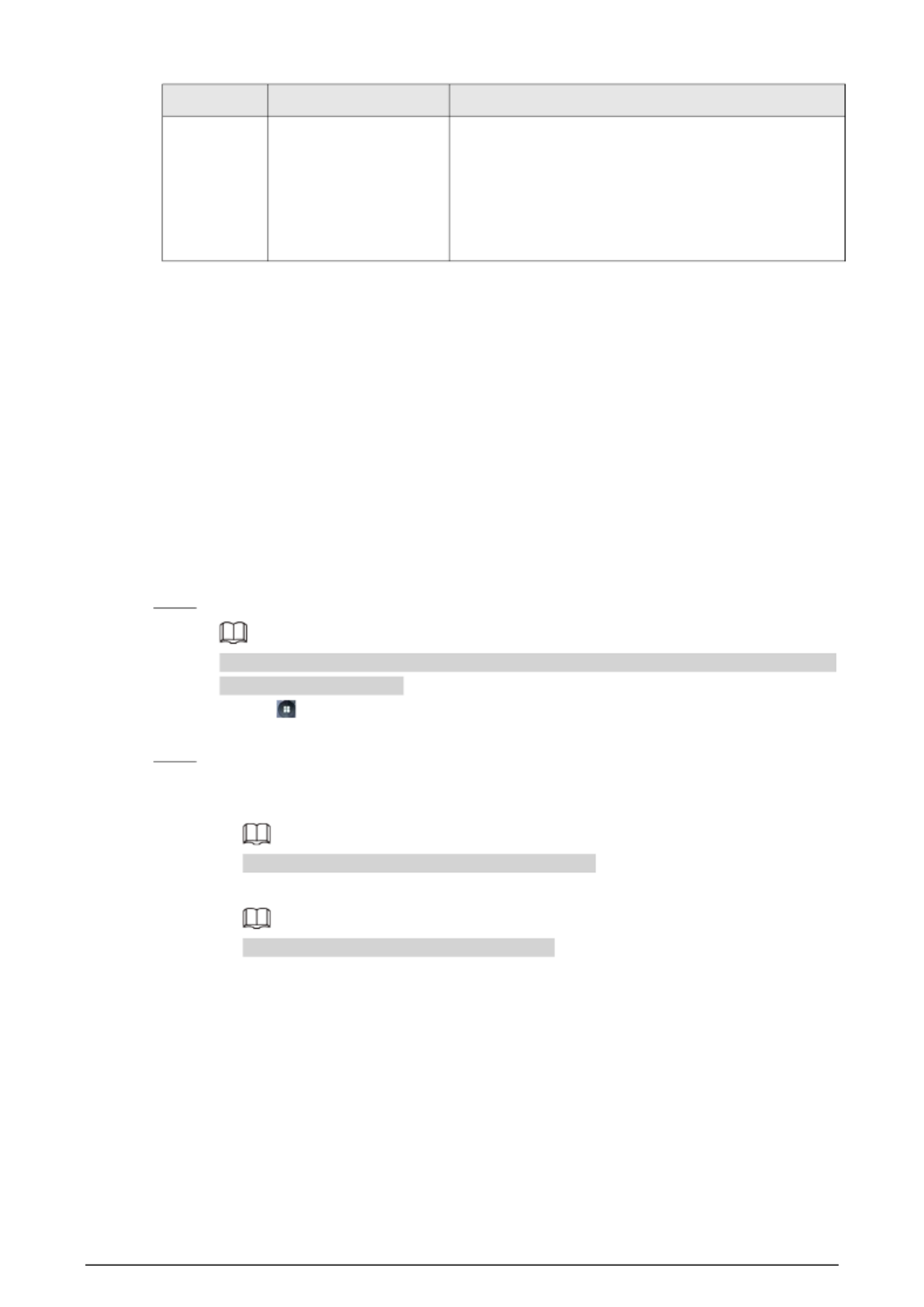
Table 2- 1 Description of icons
Icon Description
Main menu icon.
Confirm icon.
Turn to the first page of the list.
Turn to the last page of the list.
Turn to the previous page of the list.
Turn to the next page of the list.
Return to the previous menu.
Turn on.
Turn off.
Delete
Home screen
Search
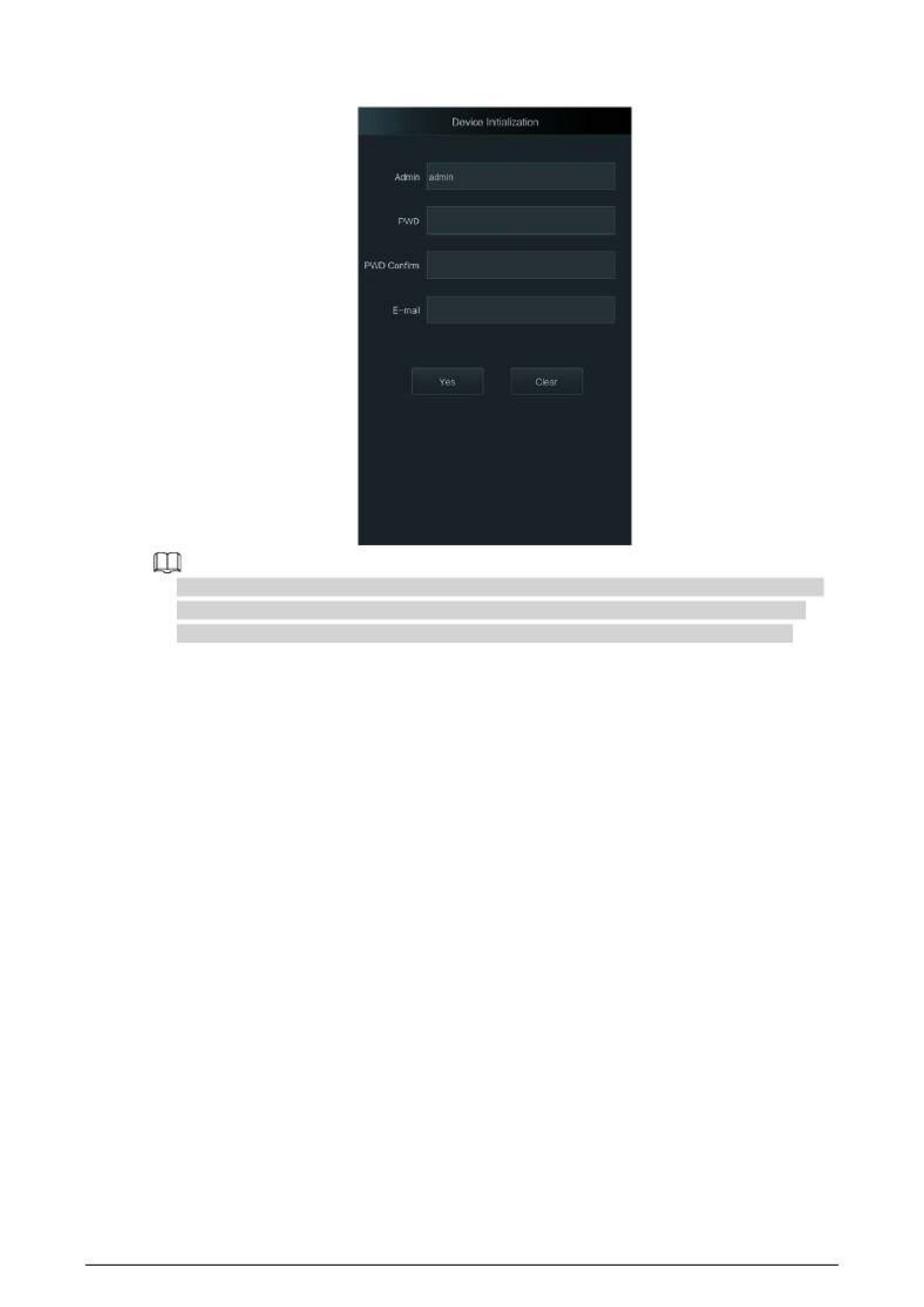
2.3 Initialization
For the first-time use or after restoring factory defaults, you need to set a password and email
address for the admin account. You can use the admin account to log in to the main menu of the
Device and the webpage.
3
Figure 2- 2 Initialization
● - If you forget the administrator password, send a reset request to your registered e mail address.
● -The password must consist of 8 to 32 non blank characters and contain at least two types of
characters among upper case, lower case, number, and special character (excluding ' " ; : &).
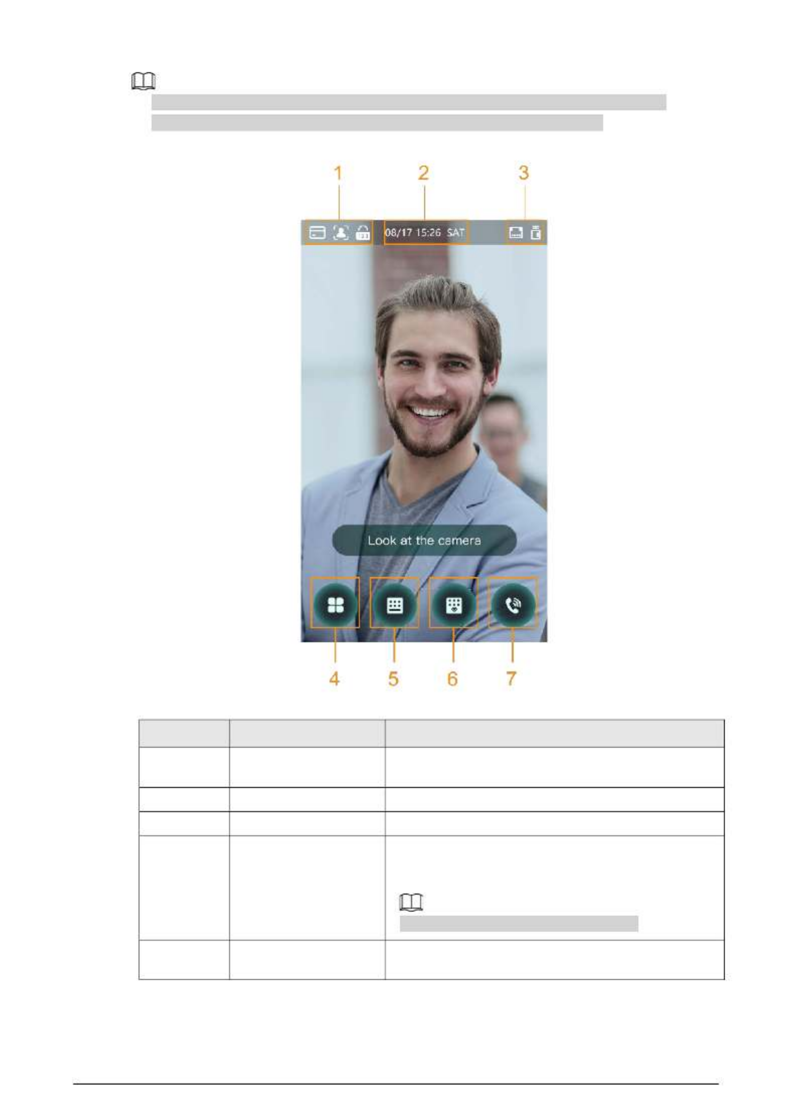
2.4 Standby Screen
You can unlock the door through faces, passwords, fingerprint, card, and their combinations.
4
● The standby screen below is for reference only, and might differ from the actual product.
● If there is no operation in 30 seconds, the Device will go to the standby mode.
Figure 2- 3 Homepage
Table 2- 2 Home screen description
No. Description Name
1 Unlock methods Displays the unlock methods supported by the Access
Controller.
2 Date and time Current date and time.
3 - Status display Displays status of Wi Fi, network, or USB.
4 Main menu icon
Log in to the main menu of the Device. Only admin
account and users with administrator permission can
enter the main menu.
Only certain types of model has this icon.
5/6 Password Enter user password or administrator password to
unlock the door.
5
No. Description Name
7 Intercom
● When the Device functions as a server, it can call
the VTO and VTH.
● When DSS functions as a server, The Access
Controller can call the VTO, VTS and DSS.
Tap the icon, enter the room number to call the home
owner.
2.5 Logging In
Log in to the main menu to configure the Device. Only admin account and administrator account
can enter the main menu of the Device. For the first-time use, use the admin account to enter the
main menu screen and then you can create the other administrator accounts.
Background Information
● Admin account: Can log in to the main menu screen of the Access Controller, but has no door
access permission.
● Administration account: Can log in to the main menu of the Access Controller and has door
access permissions.
Procedure
Step 1 Enter the verification screen.
There are 2 methods to enter the identity verification screen. Different models of products
support different methods.
● Tap on the standby screen.
● Press and hold the standby screen for 3 seconds, and then swipe left or right.
Step 2 Select a verification method to enter the main menu.
● Face: Enter the main menu by face recognition.
● Fingerprint: Enter the main menu by using fingerprint.
Fingeprint unlock is only available on select models.
● Card Punch: Enter the main menu by swiping card.
Card punch is only available on select models.
● PWD: Enter the user ID and password of the administrator account.
● admin: Enter the admin password to enter the main menu.
2.6 Network Communication
Configure the network, serial port and Wiegand port to connect the Access Controller to the
network.

6
The serial port and the wiegand port might differ depending on models of Access Controller.
2.6.1 Configuring IP
Set IP address for the Device to connect it to the network. After that, you can log in to the webpage
and the management platform to manage the Device.
Procedure
Step 1 On the Main Menu, select Connection > Network > IP Address.
Step 2 Configure IP Address.
Figure 2- 4 IP address configuration
Dual NICs (Network Interface Card) is only available on select models.
Table 2- 3 IP configuration parameters
Parameter Description
IP Address/Subnet Mask/Gateway
Address
The IP address, subnet mask, and gateway IP address
must be on the same network segment.
DHCP
It stands for Dynamic Host Configuration Protocol.
When DHCP is turned on, the Device will automatically be
assigned with IP address, subnet mask, and gateway.
P2P
P2P (peer-to-peer) technology enables users to manage
devices without applying for DDNS, setting port mapping
or deploying transit server.
2.6.2 Active Register
You can turn on the automatic registration function to access the Device through the management

7
platform.
Procedure
Step 1 On the Main Menu, select Connection > Network > Active Register.
The management platform can clear all personnel configurations and initialize the Device.
To avoid data loss, keep the management platform permissions properly.
Figure 2- 5 Auto register
Step 2 Turn on the automatic registration function and set the parameters.
Table 2- 4 Auto registration
Parameter Description
Server Address The IP address of the management platform.
Port The port No. of the management platform.
Device ID
Enter the device ID (user defined).
When you add the Device to the management platform, the
device ID on the management platform must conform to the
defined device ID on the Device.
Step 3 Enable the active register function.
2.6.3 Configuring Wi- Fi
You can connect the Device to the network through Wi Fi network. Wi- -Fi function is only available
for certain models of the Access Controller.
Procedure
Step 1 On the Main Menu, select ConnectionNetwork > WiFi.
Step 2 - Turn on Wi Fi.
Step 3 Tap to search available wireless networks.
Step 4 Select a wireless network and enter the password.

8
If no Wi-Fi is searched, tap SSID - to enter the name of Wi Fi.
Step 5 Tap
2.6.4 Configuring Serial Port
Procedure
Step 1 On the Main Menu, select Connection > Serial Port.
Step 2 Select a port type.
● t Selec Serial Input when the Access Controller connects to a card reader.
● Select Serial Output when the Access Controller functions as a card reader, and the
Access Controller will send data to the Device to control access.
Output Data type:
◇ Card: Outputs data based on card number when users swipe card to unlock door;
outputs data based on user's first card number when they use other unlock
methods.
◇ No.: Outputs data based on the user ID.
● Select OSDP Input when the Access Controller is connected to a card reader based on
OSDP protocol.
● Security Module: When a security module is connected, the exit button, lock and fire
alarm linkage will be not effective.
Figure 2- 6 Serial port
2.6.5 Configuring Wiegand
The Device allows for both Wiegand input and output mode.
Procedure
Step 1 On the Main Menu, select Connection > Wiegand.
Step 2 Select a Wiegand.
● Select Wiegand Input when you connect an external card reader to the Device.
● Select Wiegand Output when the Device functions as a card reader, and you need to
connect it to a controller or another access terminal.

9
Figure 2- 7 Wiegand output
Table 2- 5 Description of Wiegand output
Parameter Description
Wiegand Output Type
Select a Wiegand format to read card numbers or ID numbers.
● Wiegand26: Reads three bytes or six digits.
● Wiegand34: Reads four bytes or eight digits.
● Wiegand66: Reads eight bytes or sixteen digits.
Pulse Width Enter the pulse width and pulse interval of Wiegand output.
Pulse Interval
Output Data Type
Select the type of output data.
● User ID: Outputs data based on user ID.
● Card No.: Outputs data based on user's first card number.
2.7 User Management
You can add new users, view user/admin list and edit user information.
The pictures in this manual are for reference only, and might differ from the actual product.
2.7.1 Adding New Users
Procedure
Step 1 On the Main Menu, select User > New User.
Step 2 Configure the parameters.

10
The parameters of new users might differ depending on the models of the product.
Figure 2- 8 New user
Table 2- 6 Description of new user parameters
Parameter Description
User ID
Enter user IDs. The IDs can be numbers, letters, and their
combinations, and the maximum length of the ID is 32 characters.
Each ID is unique.
Name Enter name with at most 32 characters (including numbers, symbols,
and letters).
FP
At most 3 fingerprints can be registered for each user.
You can set one of the registered fingerprints to duress fingerprint.
After the duress function is turned on, an alarm will be triggered
when a duress fingerprint is used to unlock the door.
It is not recommended that you set the first fingerprint as the
duress fingerprint.
Face
Make sure that your face is centered on the image capturing frame,
and an image of the face will be captured and analyzed
automatically.

11
Parameter Description
Card
A user can register 5 cards at most. Enter your card number or swipe
your card, and then the card information will be read by the Device.
You can enable the Duress Card function. An alarm will be triggered
if a duress card is used to unlock the door.
Only certain models support card unlock.
PWD Enter the user password. The maximum length of the password is 8
digits.
User Level
You can select a user level for new users.
● User: Users only have door access permission.
● Admin: Administrators can unlock the door and configure the
access controller.
Period People can unlock the door only during the defined period.
Holiday Plan People can unlock the door only during the defined holiday plan.
Valid Date Set a date on which the access permissions of the person will be
expired.
User Type
● General: General users can unlock the door.
● Blocklist: When users in the blocklist unlock the door, service
personnel will receive a notification.
● Guest: Guests can unlock the door within a defined period or for
certain amount of times. After the defined period expires or the
unlocking times runs out, they cannot unlock the door.
● Patrol: Patrol users will have their attendance tracked, but they
have no unlocking permissions.
● VIP: When VIP unlock the door, service personnel will receive a
notice.
● Others: When they unlock the door, the door will stay unlocked
for 5 more seconds.
● Custom User 1/Custom User 2: Same with general users.
Use Time When the user level is set to guest, you can set the maximum
number of times that the user can unlock the door.
Step 3 Tap to save the configuration.
2.7.2 Viewing User Information
You can view user/admin list and edit user information.
Procedure
Step 1 On the Main Menu, select User > User List, or select User > Admin List.
Step 2 View all added users and admin accounts.

12
Figure 2- 9 Admin list
● : Unlock through password.
● : Unlock through swiping card.
● : Unlock through face recognition.
● : Unlock through fingerprint.
Related Operations
On the User screen, you can manage the added users.
● Search for users: Tap and then enter the username.
● Edit users: Tap the user to edit user information.
● Delete users
◇ Delete individually: Select a user, and then tap . .
◇ Delete in batches:
○ On the User List screen, tap to delete all users.
○ On the Admin List screen, tap to delete all admin users.
2.7.3 Configuring Administrator Password
You can unlock the door by only entering the admin password. Admin password is not limited by
user types. Only one admin password is allowed for one device.
Procedure
Step 1 On the Main Menu screen, select User > Administrator PWD.
Figure 2- 10 Set admin password

13
Step 2 Tap Administrator PWD, and then enter the administrator password.
Step 3 . Tap
Step 4 Turn on the administrator function.
2.8 Access Management
You can configure door access parameters, such as unlocking modes, alarm linkage, door schedules.
Unlock modes might differ depending on the actual product.
2.8.1 Configuring Unlock Combinations
Use card, fingerprint, face or password or their combinations to unlock the door.
Procedure
Step 1 Select Access > Unlock Mode > Unlock Mode.
Step 2 Select unlocking methods.
To cancel your selection, tap the selected method again.
Step 3 Tap +And or /Or to configure combinations.
● +And: Verify all the selected unlocking methods to open the door.
● /Or: Verify one of the selected unlocking methods to open the door.

14
Figure 2- 11 Element (multiple choice)
Step 4 Tap to save changes.
2.8.2 Configuring Unlock by Period
Doors can be unlocked through different unlock modes in different periods. For example, in period
1, the door can only be unlocked through card; and in period 2, doors can only be locked through
fingerprints.
Procedure
Step 1 Select Access > Unlock Mode > Unlock by Period.
Step 2 Set starting time and end time for a period, and then select a unlock mode.

15
Figure 2- 12 Unlock by period
Step 3 Tap to save changes.
Step 4 Turn on the unlock by period function.
2.8.3 Configuring Group Combination
Doors can only be unlocked by a group or groups that consist of more than two users if the Group
Combination is enabled.
Procedure
Step 1 Select Access > Unlock Mode > Group Combination .
Step 2 Tap to create a group.
Figure 2- 13 Add group
Table 2- 7 Group combination description
Parameter Description
16
User List
Add users to the newly created group.
1. Tap User List.
2. Tap , and then enter a user ID.
3. Tap to save the settings.
Unlock Mode There are four options: Card, FP,PWD and Face.
Valid User
Valid users are the ones that have unlock authority. Doors can be unlocked
only when the number of users to unlock the doors equals the valid user
number.
● Valid users cannot exceed the total number of users in a group.
● If valid users equal total user numbers in a group, doors can only be
unlocked by all the users in the group.
● If valid users are less than the total number of users in a group, doors
can be unlocked by any users whose number equals the valid user
number.
Step 3 Tap to go back to the previous interface.
Step 4 to Tap save the changes.
Step 5 Turn on the group combination function.
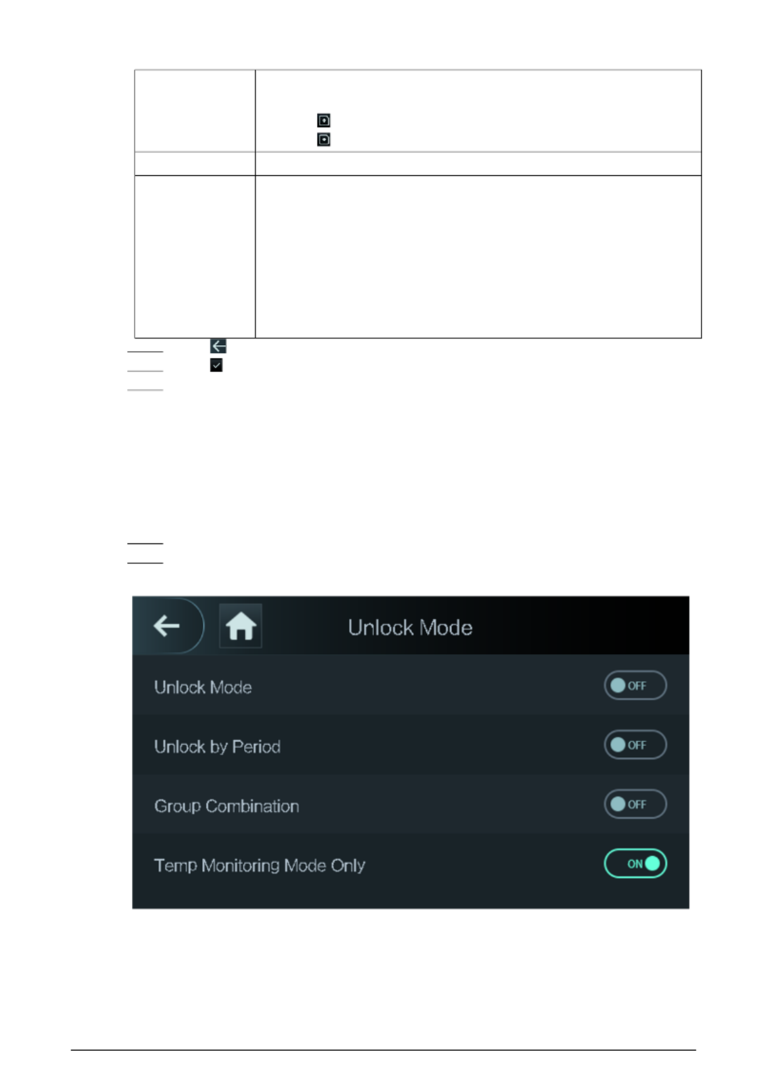
2.8.4 Unlocking by Monitoring Temperature
Control access only through temperature monitoring. This function is only available on select
models.
Procedure
Step 1 Select Access > Unlock Mode.
Step 2 Enable Temp Monitoring Mode Only.
Figure 2- 14 Temperature monitoring only

17
2.8.5 Configuring Alarm
An alarm will be triggered when abnormal access events occur.
Procedure
Step 1 Select Access > Alarm.
Step 2 Enable the alarm type.
Alarm types might differ depending on the models of the product.
Figure 2- 15 Alarm
Table 2- 8 Description of alarm parameters
Parameter Description
Anti- passback
Users need to verify their identities both for entry and exit; otherwise
an alarm will be triggered. It helps prevents a card holder from passing
an access card back to another person so they gain entry. When anti-
passback is enabled, the card holder must leave the secured area
through an exit reader before system will grant another entry.
● If a person enters after authorization and exits without
authorization, an alarm will be triggered when they attempt to
enter again, and access is denied at the same time.
● If a person enters without authorization and exits after
authorization, an alarm will be triggered when the they attempt to
enter again, and access is denied at the same time.
Duress An alarm will be triggered when a duress card, duress password or
duress fingerprint is used to unlock the door.
Illegal Card Exceeding
Time
After an unauthorized card is used to unlock the door more than 5
times in 50 seconds, an alarm will be triggered.
Intrusion When door sensor is enabled, an intrusion alarm will be triggered if
the door is opened abnormally.

18
Parameter Description
Door Sensor Timeout
A timeout alarm will be triggered if the door remains unlocked longer
than the defined door sensor timeout, which ranges from 1 to 9999
seconds.
Door Sensor On Intrusion and timeout alarms can be triggered only after door sensor is
enabled.
2.8.6 Configuring Door Status
Procedure
Step 1 On the Main Menu screen, select Access > Door Status.
Step 2 Set door status.
● NO: The door remains unlocked all the time.
● NC: The door remains locked all the time.
● Normal: If Normal is selected, the door will be unlocked and locked according to your
settings.
2.8.7 Configuring Lock Holding Time
After a person is granted access, the door will remain unlocked for a defined time for them to pass
through.
Procedure
Step 1 On the Main Menu, select Access > Lock Holding Time.
Step 2 Enter the unlock duration.
Step 3 Tap to save changes.
2.9 Period Management
You can set periods, holiday periods, holiday plan periods, door normally open periods, door
normally closed periods, and remote verification periods.
2.9.1 Configuring Period
You can configure up to 128 periods. In each period, you need to edit door access schedules for a
whole week. A user can only unlock the door during the scheduled time.
Procedure
Step 1 Log in to the Main Menu screen.
Step 2 Select Access > Period > Period Config.
Step 3 on Tap the upper- right corner.
Step 4 Enter No. and period name.
● No: Enter a section No. It ranges between 0 to 127.
● Period Name: Enter a name for the period. You can enter 10 Chinese characters or 32
characters (contain number, special characters and English characters).
Step 5 Configure time for a week.
Step 6 You can configure up to four periods for a single day.

19
Step 7 Tap to save changes.
2.9.2 Configuring Holiday Groups
Set time sections for different holiday groups. You can configure up to 128 holiday groups (from
No.0 through No.127), and up to 16 holidays for a single holiday group.
Procedure
Step 1 Log in to the Main Menu screen.
Step 2 Select Access > Period > Holiday Group Config.
Step 3 on the upper Tap - right corner.
Step 4 Enter a number and a name for the holiday group.
● No.: Enter a period name. It ranges from 0 through 127.
● Holiday Group Name: Enter a name for each holiday group. You can enter 10 Chinese
characters or 32 characters (contain numbers, special characters and English
characters).
Step 5 Tap Group Config, and then tap .
Step 6 Enter the serial number and holiday name, and then select the start date and end date.
Step 7 Tap to save changes.
2.9.3 Configuring Holiday Plan
Assign the configured holiday groups to the holiday plan. Users can only unlock the door in the
defined time sections in the holiday plan.
Procedure
Step 1 Log in to the Main Menu screen.
Step 2 SelectAccess > Period > Holiday Plan Config.
Step 3 on the upper Tap - right corner.
Step 4 Enter a number and name for the holiday plan.
● No.: Enter a number of the holiday plan. It ranges from 0 through 127.
● Holiday Plan Name: Enter a name for each time section. You can enter 10 Chinese
characters or 32 characters (contain numbers, special characters and English
characters).
Step 5 Select Holiday Group No., and enter the holiday group No. that you have configured.
Step 6 Select Holiday Period , configure time periods for a single holiday.
Step 7 Tap to save changes.
2.9.4 Configuring NO Period
If you configure NO period, the door remains open in the defined period. The NO/NC period
overrides other periods.
Procedure
Step 1 Log in to the Main Menu interface.
Step 2 Select Access > Period > NO Period.
Step 3 Enter the period No. that you have configured.
Step Tap 4 to save changes.
20
2.9.5 Configuring NC Period
If you configure NC period, the door remains unlocked in the defined period. The NO/NC period
overrides other periods.
Procedure
Step 1 On the Main Menu screen, select Access > Period > NO Period.
Step 2 Enter the period No. that you have configured.
Step 3 Tap to save changes.
2.9.6 Configuring Remote Verification Period
Procedure
Step 1 Log in to the Main Menu screen
Step 2 On the Main Menu, select Access > Period > Remote Verification Period.
Step 3 Enable Remote Verification Period .
Step 4 Enter the period No. that you have configured.
Step 5 Tap to save changes.
2.10 Attendance Management
You can turn on the time attendance function, and employee can make their attendance tracked by
the Device at the same time when they unlock the door. This function is only available on select
models.
Procedure
Step 1 On the main menu, tap Attendance, and then turn on the attendance function.
Step 2 Tap Mode Set.
Step 3 Select an attendance mode.
Step 4 the parameters for the attendance mode. Configure
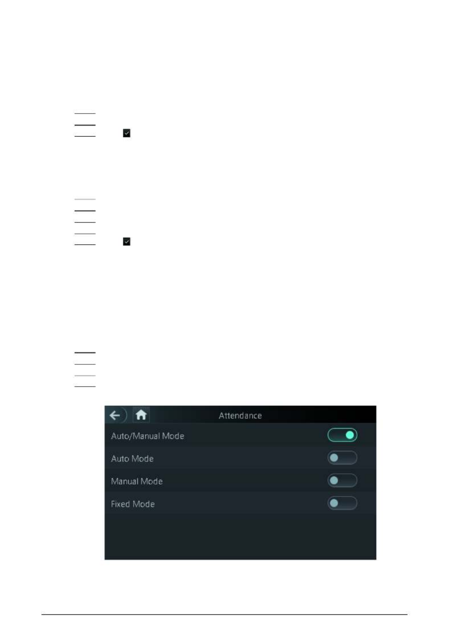
Figure 2- 16 Attendance mode

21
Table 2- 9 Attendance mode description
Parameter Description
Auto/Manual Mode After you clock in/out, you can manfully select the attendance status
or the screen displays the time attendance status automatically.
Auto Mode The screen displays attendance status automatically after you clock
in/out.
Manual Mode Clock in/out and then tap Attendance status to manfully select the
attendance status.
Fixed Mode When you clock the screen will displays the pre in/out, -configured
attendance status all the time.
Table 2-10 Attendance mode parameters
Parameters Description
Check In Clock in when your normal workday starts.
Break Out Clock out when your leave of absence ends.
Break In Clock in when your leave of absence starts.
Check Out Clock out when your normal workday starts.
OT- In Clock in when your overtime working hours starts.
OT- Out Clock out when your overtime working hours ends.
2.11 System
2.11.1 Configuring Time
Configure system time, such as date, time, and NTP.
Procedure
Step 1 On the Main Menu, select System > Time.
Step 2 Configure system time.
22
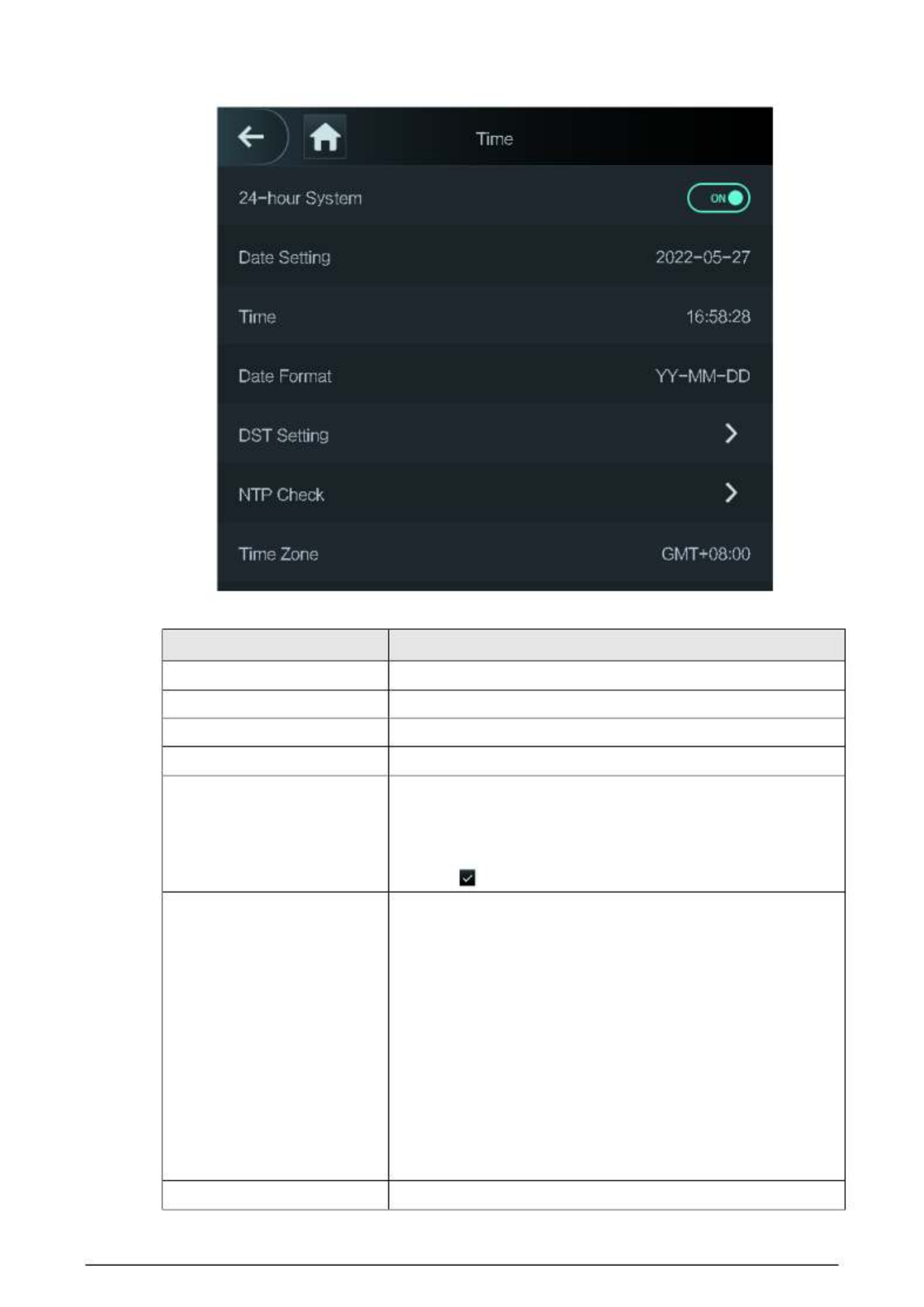
Figure 2- 17 Time
Table 2- 11 Description of time parameters
Parameter Description
24- - hour System The time is displayed in 24 hour format.
Date Setting Set up the date.
Time Set up the time.
Date Format Select a date format.
DST Setting
1. Tap DST Setting.
2. Enable DST.
3. Select Date or Week from the DST Type list.
4. Enter start time and end time.
5. . tap
NTP Check
A network time protocol (NTP) server is a machine dedicated as
the time sync server for all client computers. If your computer is
set to sync with a time server on the network, your clock will
show the same time as the server. When the administrator
changes the time (for daylight savings), all client machines on
the network will also update.
1. Tap NTP Check.
2. . Turn on the NTP check function and configure parameters
● Server IP Address: Enter the IP address of the NTP
server, and the Device will automatically sync time with
NTP server.
● Port: Enter the port of the NTP server.
● Interval (min): Enter the time synchronization interval.
Time Zone Select the time zone.

23
2.11.2 Configuring Face Parameters
Procedure
Step 1 On the main menu, select System > Face Parameter.
We recommend professional personnel to configure face parameters.
Step 2 . Configure the face parameters, and then tap
The picture below is for reference only, and face parameters might differ depending on
models of the product.
Figure 2- 18 Face parameter
Table 2- 12 Description of face parameters
Name Description
Face Threshold Adjust the face recognition accuracy. Higher threshold means
higher accuracy.
Max. Angle of Face
Set the maximum face pose angle for face detection. Larger value
means larger face angle range. If the face pose angle is out of the
defined range, the face detection box will not appear.
Pupillary Distance
Face images require desired pixels between the eyes (called
pupillary distance) for successful recognition. The default pixel is
45. The pixel changes according to the face size and the distance
between faces and the lens. If an adult is 1.5 meters away from
the lens, the pupillary distance can be 50 px- 70 px.
Recognition Timeout (S)
If a person with access permission has their face successfully
recognized, the Device will prompt face recognition success. You
can enter the prompt interval time.
Invalid Face Prompt Interval
(S)
If a person without access permission attempts to unlock the
door for several times in the defined interval, the Device will
prompt face recognition failure. You can enter the prompt
interval time.

24
Name Description
Temp Parameters
Only Device with temperature monitoring supports this function.
● Temperature Monitoring: Enable or disable this function.
● Temp Rect: Set whether to display the temperature
monitoring box or not.
● Temp Monitoring Distance (cm): 50 by default. You must
monitor your temperature standing away from the Device at
the distance you define.
● Temp Correction Duration (ms): When monitoring the
temperature, the Device will take the temperature value after
the time defined by this parameter.
● High Temp Threshold: Set the temperature threshold. The
monitored body temperature will be judged as high
temperature if it is greater than or equal to the set value.
● Max/Min temperature: Set the temperature range you need.
If the monitored temperature is lower than the lower limit, it
will prompt that the temperature is too low; if higher than
the upper limit, it will prompt that there is a heat source
interfering with the function.
● Temp Correction Value: This parameter is for testing. The
difference of the temperature monitoring environment
might cause the temperature deviation between the
monitored temperature and the actual temperature. You can
select multiple monitored samples for testing, and then
correct the temperature deviation by this parameter
according to the comparison between the monitored
temperature and the actual temperature. For example, if the
monitored temperature is 0.5°C lower than the actual
temperature, the correction value is set to 0.5°C; if the
monitored temperature is 0.5°C higher than the actual
temperatu - re, the correction value is set to 0.5°C.
● Temp Monitoring Mode:
◇ Auto: Uses a face heat map for face recognition; if heat
maps are not found, it will automatically change to
calibration mode.
◇ Thermogram: Uses only a heat map for face recognition
and temperature monitoring.
◇ Calibration: Uses a white light image of a face for face
recognition, and then extract and apply the coordinates
on the face heat map for temperature monitoring.
● t° Temp Unit: Selec C or° F.
● Evn Compensation Value: This value will be added to the
monitored environment temperature.
Anti- fake Threshold Avoid false face recognition by using a photo, video, mask or a
different substitute for an authorized person's face.
Mask Parameters ● Mask mode:

25
Name Description
◇ No detect: Mask is not detected during face recognition.
◇ Mask reminder: Mask is detected during face
recognition. If the person is not wearing a mask, the
system will remind them to wear masks, and access is
allowed.
◇ Mask intercept : Mask is detected during face recognition.
If a person is not wearing a mask, the system will remind
them to wear masks, and access is denied.
● Mask Recognition Threshold: Higher threshold means higher
mask detection accuracy.
2.11.3 Configuring Image Mode
Configure the image mode based on the installation site.
Procedure
Step 1 On the Main Menu, select System > Image Mode.
Step 2 Select image mode according to the installation location.
● Indoor: The Device is usually installed indoor such as offices. The artificial light is even
across the room and there is no daylight.
● Outdoor: The Device is usually installed outdoor and the daylight is bright and even.
● -Other: When human face is in back lighting which makes the face dim, we recommend
you select other mode to make it easier for the Access Controller to detect.
Figure 2- 19 Image mode
2.11.4 Configuring Fill Light Mode
You can select the modes of the fill light based on the actual environment. There are three modes.
● Auto: When the fill light is automatically turned on when the ambient environment is dark, and it
is automatically off when there is a lot of light.
● NO: The fill light is normally open.
● NC: The fill light is normally closed.

26
2.11.5 Configuring the Brightness of Fill Light
You can select the brightness of the fill light based on the actual environment.
2.11.6 Configuring the Brightness of IR Light
The larger the value is, the clearer the images will be; otherwise the unclearer the images will be.
2.11.7 Configuring Fingerprint Parameters
Set the fingerprint accuracy level. The higher the level is, the lower the false recognition rate will be.
This function is only available on select models.
2.11.8 Setting Volume
Procedure
Step 1 On the Main Menu, select System > Volume.
Step 2 Select Beep Volume or Mic Volume.
Step 3 or Tap to adjust the volume.
2.11.9 Restoring Factory Defaults
Procedure
Step 1 On the Main Menu, select System > Restore Factory.
Step 2 Restore factory defaults if necessary.
● Restore Factory: Resets all configurations except for configurations of IP and the type
of extension module.
● Restore Factory (Save user & log): Resets all configurations except for user
information and logs.
2.11.10 Restart the Device
On the Main Menu, select System > Reboot, and the Device will be restarted.
2.12 USB Management
You can use a USB to update the Device, and export or import user information through USB.

27
● Make sure that a USB is inserted to the Device before you export data or update the system. To
avoid failure, do not pull out the USB or perform any operation of the Device during the process.
● You have to use a USB to export the information from an Access Controller to other devices. Face
images are not allowed to be imported through USB.
2.12.1 Exporting to USB
You can export data from the Device to a USB. The exported data is encrypted and cannot be edited.
Procedure
Step 1 On the Main Menu, select USB > USB Export.
Step 2 Select the data type you want to export, and then tap OK.
Figure 2- 20 USB export
2.12.2 Importing From USB
You can import data from USB to the Device.
Procedure
Step 1 On the Main Menu, select USB > USB Import.
Step 2 Select the data type that you want to export, and then tap OK.

28
Figure 2- 21 USB import
2.12.3 Updating System
Use a USB to update the system of the Device.
Procedure
Step 1 Rename the update file to "update.bin", put it in the root directory of the USB, and then
insert the USB to the Device.
Step 2 On the Main Menu, select USB > USB Update.
Step 3 Tap OK.
The Device will restart when the updating completes.
2.13 Configuring Features
On the Main Menu, tap Features.
Features might differ depending on the models of the product.

29
Figure 2 22 Configure features-
Table 2- 13 Description of features
Parameter Description
Private Setting
● PWD Reset Enable: You can enable this function to reset
password. The PWD Reset function is enabled by default.
● HTTPS: Hypertext Transfer Protocol Secure (HTTPS) is a protocol
for secure communication over a computer network.
When HTTPS is enabled, HTTPS will be used to access CGI
commands; otherwise HTTP will be used.
When HTTPS is enabled, the Device will restart automatically.
● CGI: Common Gateway Interface (CGI) offers a standard
protocol for web servers to execute programs similarly to
console applications running on a server that dynamically
generates web pages.
The CG I is enabled by default.
● SSH: Secure Shell (SSH) is a cryptographic network protocol for
operating network services securely over an unsecured
network.
● Capture Photos: Face images will be captured automatically
when people unlock the door. The function is enabled by
default.
● Debug Mode: Enable this mode to display the temperature of
the blackbody on the standby interface. You can correct the
temperature of the blackbody accordingly.

30
Parameter Description
When this mode is enabled, the door cannot be opened by any
method.
● Temperature Display: If it is enabled, the temperature will be
displayed when you unlock the door.
● Clear all captured photos: Deletes all captured photos.
● Face Privacy: Set different levels to blur the face image on the
standby screen.
Card No. Reverse
When the Access Controller connects to a third-party device
through Wiegand input, and the card number read by the Access
Controller is in the reserve order from the actual card number, you
need to turn on the Card No. Reverse function.
Security Module
● The security module does not come with the product and it
needs to be purchased separately by the customer. The
security module needs separate power supply.
● When the security module is turned on, the exit button, lock
control and firefighting linkage will be invalid.
Thermogram Display - Display a heat map at the upper left corner.
External Reader Temp
Monitoring
Turn it on and the card reader will also monitor the temperature of
a person.
Door Sensor
NC: When the door opens, the circuit of the door sensor circuit is
closed.
NO: When the door opens, the circuit of the door sensor circuit is
open.
Intrusion and overtime alarms are triggered only after door
detector is turned on.
Result Feedback
● Success/Failure: Only displays success or failure on the standby
screen.
● Only Name: Displays user ID, name and authorization time after
access granted; displays not authorized message and
authorization time after access denied.
● Photo&Name: Displays user's registered face image, user ID,
name and authorization time after access granted; displays not
authorized message and authorization time after access
denied.
● Photos&Name: Displays the captured face image and a
registered face image of a user, user ID, name and
authorization time after access granted; displays not
authorized message and authorization time after access
denied.
2.14 Unlocking the Door
You can unlock the door through faces, passwords, cards, and more. The default unlock methods are
card/face/password.

31
Unlock methods might differ depending on models of the product.
2.14.1 Unlocking by Cards
Place the card at the swiping area to unlock the door.
2.14.2 Unlocking by Face
Verify the identity of an individual by detecting their faces. Make sure that your face is centered on
the face detection frame.
2.14.3 Unlocking by User Password
Enter the user ID and password to unlock the door.
Procedure
Step 1 Tap on the standby screen.
Step 2 tap PWD Unlock, and then enter the user ID and password.
Step 3 Tap Yes.
2.14.4 Unlocking by Administrator Password
Enter only the administrator password to unlock the door. The Device only allows for one
administrator password. Using administrator password to unlock the door without being subject to
user levels, unlock modes, periods, holiday plans, and anti passback except for normally closed door. -
One device allows for only one admin password.
Prerequisites
The administrator password was configured. For details, see "2.7.3 Configuring Administrator
Password".
Background Information
Administrator password cannot be used to unlock the door status is set to NC.
Procedure
Step 1 Tap on the standby screen.
Step 2 Tap Admin PWD, and then enter the admin password.
Step 3 . Tap

32
2.14.5 Unlocking by Fingerprint
Place you finger on the fingerprint scanner. This function is only available on models. select
2.15 Viewing Unlock Records
You can view door unlock records.
Figure 2- 23 Search records
2.16 Configuring Self- test
When you use the Device for the first time or when the Device malfunctioned, you can use auto test
function to check whether the Device can work normally. Test according to the screen prompts. Test

33
items might differ depending on the models of the product.
Figure 2- 24 Self test
Table 2- -14 Self test
Parameter Description
Screen Test whether the screen is normal.
Voice Test whether the voice is normal.
Button Test whether the voice is normal.
FP Test whether the fingerprint recognition is normal.
Face Test whether the face recognition is normal.
Clock Test whether the clock is normal.
Auto Test All the items above will be tested automatically.
Self Test The Device automatically tests RTC clock, network card,
fingerprint chips, and cameras, and it gives test results.
2.17 System Information
You can view data capacity and device version.
2.17.1 Viewing Data Capacity
On the Main Menu, select System Info > Data Capacity, you can view storage capacity of each data

34
type.
2.17.2 Viewing Device Version
On the Main Menu, select System Info > Data Capacity, you can view the device version, such as
serial No., software version and more.

35
3 Web Operations
On the webpage, you can also configure and update the Device.
Web configurations differ depending on models of the Device.
3.1 Initialization
Initialize the Device when you log in to the webpage for the first time or after the Device is restored
to the factory defaults.
Prerequisites
Make sure that the computer used to log in to the webpage is on the same LAN as the Device.
Procedure
Step 1 Open a browser, go to the IP address (the default address is 192.168.1.108) of the Device.
We recommend you use the latest version of Chrome or Firefox.
Step 2 Set the password and email address according to the screen instructions.
● -The password must consist of 8 to 32 non blank characters and contain at least two
types of the following characters: upper case, lower case, numbers, and special
characters (excluding ' " ; security password by following the password -: &). Set a high
strength prompt.
● Keep the password safe after initialization and change the password regularly to
improve security.
3.2 Logging In
Procedure
Step 1 Open a browser, enter the IP address of the Device in the Address bar, and press the Enter
key.
36
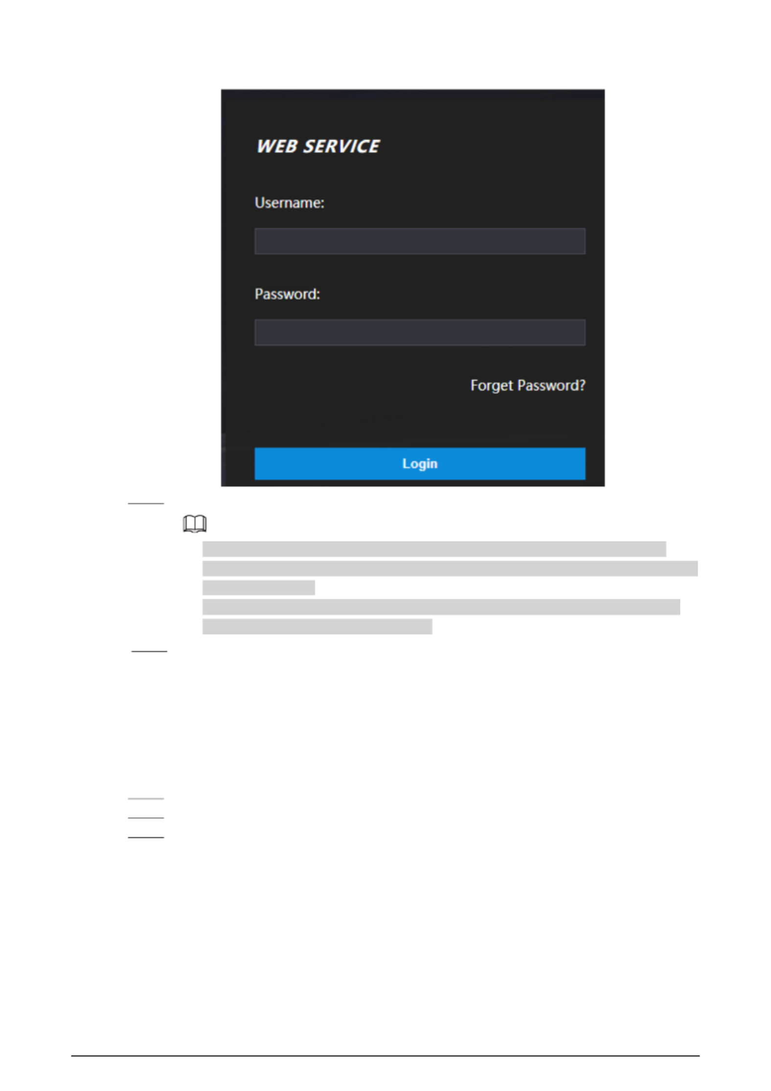
Figure 3- 1 Login
Step 2 Enter the user name and password.
● The default administrator name is admin, and the password is the one you set up
during initialization. We recommend you change the administrator password regularly
to increase security.
● If you forget the administrator login password, you can click Forget password? For
details, see "3.3 Resetting the Password".
Step 3 Click Login.
3.3 Resetting the Password
Reset the password through the linked e- mail when you forget the admin password.
Procedure
Step 1 On the login page, click Forgot password.
Step 2 Read the on -screen prompt carefully, and then click OK.
Step 3 Scan the QR code, and you will get the security code.

37
Figure 3- 2 Reset password
● Up to two security codes will be generated when the same QR code is scanned. If the
security code becomes invalid, refresh the QR code and scan again.
● -After you scan the QR code, you will receive a security code in your linked e mail
address. Use the security code within 24 hours after you receive it. Otherwise, it will
become invalid.
● If the wrong security code is entered in a row, the administrator account will be frozen
for 5 minutes.
Step 4 Enter the security code.
Step 5 Click Next.
Step 6 Reset and confirm the new password.
The password should consist of 8 to 32 non-blank characters and contain at least two of
the following types of characters: upper case, lower case, number, and special character
(excluding ' " ; : &).
Step 7 Click OK.
3.4 Configuring Door Parameter
Configure the access control parameters.
Procedure
Step 1 Log in to the webpage.
Step 2 Select Door Parameter.
38
Figure 3- 3 Door parameter
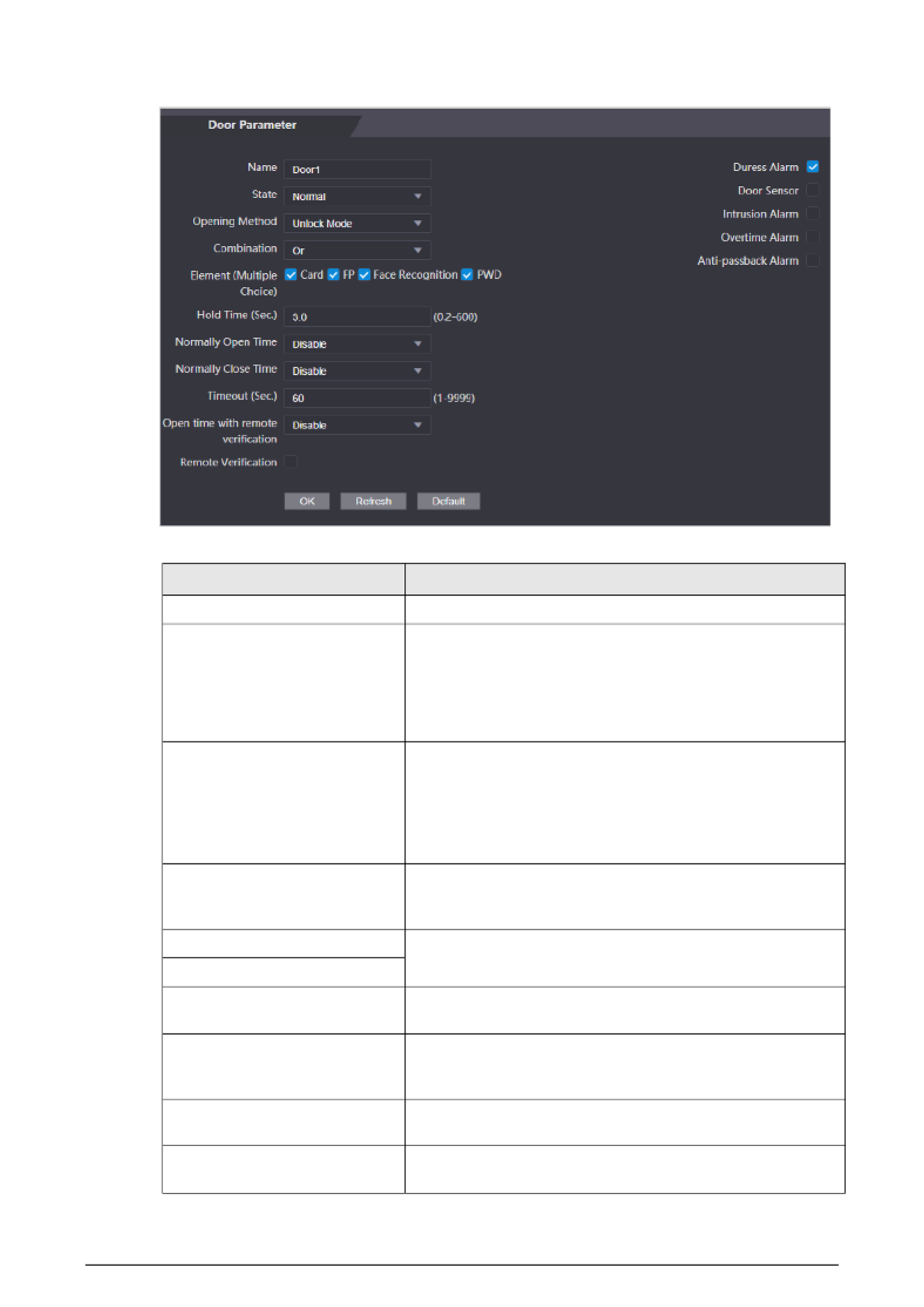
Table 3- 1 Description of door parameters
Parameter Description
Name Enter a name of the door.
State
Set the door status.
● NO: The door remains unlocked all the time.
● NC: The door remains locked all the time.
● Normal: If Normal is selected, the door will be unlocked
and locked according to your settings.
Opening Method
● Unlock by Period: Set different unlock methods for
different periods.
● Group Combination: The user can unlock the door only
after defined users or user groups grant access.
● Unlock Mode: Set unlock combinations.
Hold Time (Sec.)
After a person is granted access, the door will remain
unlocked for a defined time for them to pass through. It
ranges from 0.2 s to 600 s.
Normally Open Time The door remains open or closed during the defined period.
Normally Close Time
Timeout (Sec.) A timeout alarm will be triggered if the door remains
unlocked for longer time than this value.
Open with remote verification
Set the remote verification door opening period. After users
gain access on the Device, they must also be granted access
from the management platform before the door unlocks.
Duress Alarm An alarm will be triggered when a duress card or duress
password is used to unlock the door.
Door Sensor Intrusion and overtime alarms can be triggered only after
Door Sensor is enabled.

39
Parameter Description
Intrusion Alarm When Door Sensor is enabled, an intrusion alarm will be
triggered if the door is opened abnormally.
Overtime Alarm A timeout alarm will be triggered if the door remains
unlocked for longer time than the Timeout (Sec).
Anti-passback Alarm
Users need to verify their identities both for entry and exit;
otherwise an alarm will be triggered. It help prevents a card s
holder from passing an access card back to another person so
they gain entry. When anti-passback is enabled, the card
holder must leave the secured area through an exit reader
before system will grant another entry.
● If a person enters after authorization and exits without
authorization, an alarm will be triggered when they
attempt to enter again, and access is denied at the same
time.
● If a person enters without authorization and exits after
authorization, an alarm will be triggered when the they
attempt to enter again, and access is denied at the same
time.
Step 3 Configure the opening method.
● Unlock by Period
1. In the Opening Method list, select Unlock by Period, and then click .
Figure 3- 4 Time section parameter
2. Configure the time and the opening method for a time section. You can configure
up to four time sections for a single day.
3. Select Apply to the whole week to copy the defined time to the rest of days.
● Group Combination
1. In the Opening Method list, select Group Combination , and then click .
2. Click Add.
3. Select an unlocking method in the Opening Method list, and enter the number of
valid users. If the number of valid users is 2, and there are 3 users in the defined user
list. Two users in the list are required to grant access.
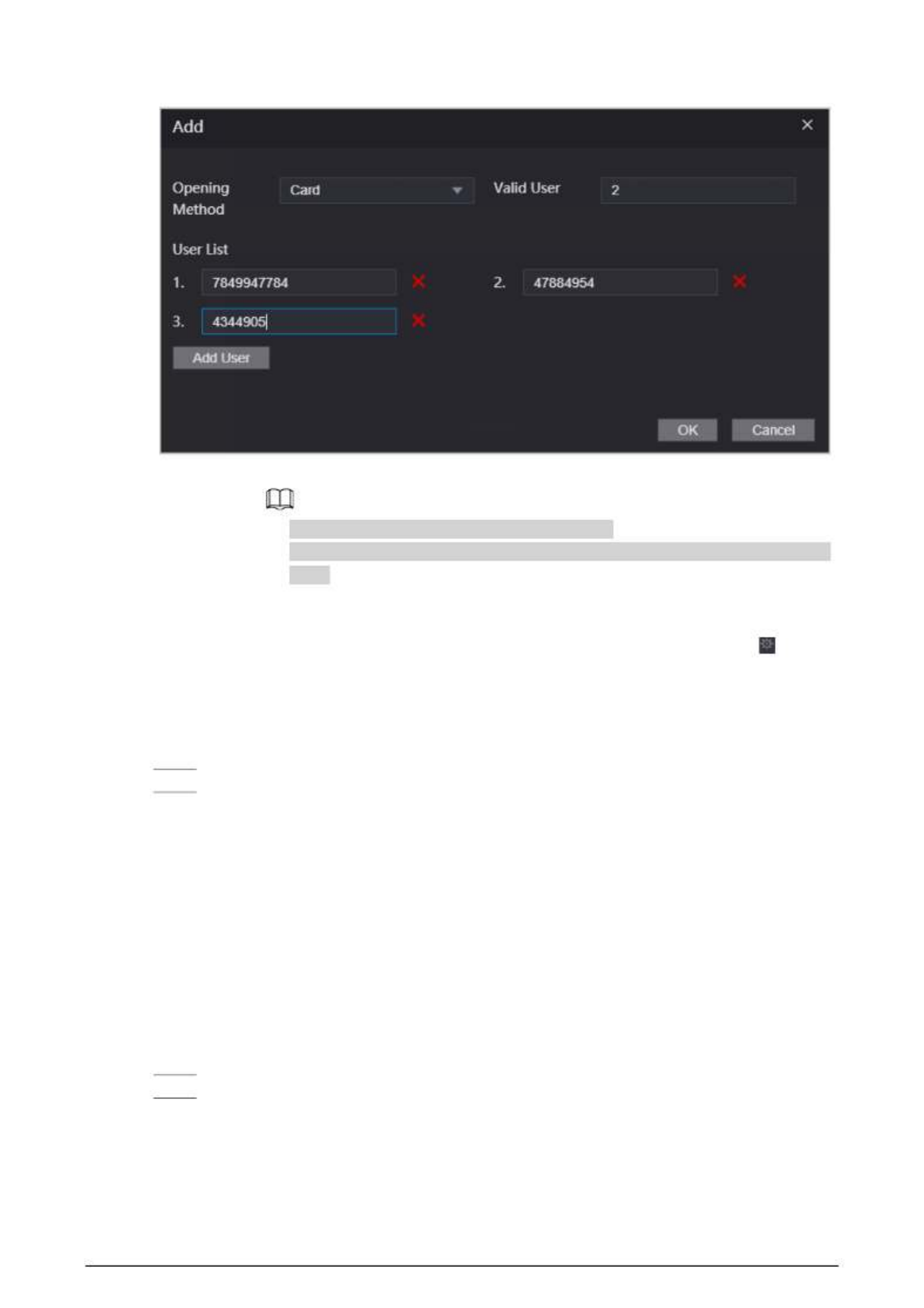
40
Figure 3- 5 Group Combination
4. In the User List area, click Add User, enter the user ID of existing users.
◇ VIP, patrol, and blocklist users cannot be added.
◇ Valid users in all groups must verify their identities to grant access in the group
order.
5. Click OK.
● Unlock mode
1. In the Opening Method list, select Group Combination , and then click .
2. In the Combination list, select Or or And.
◇ And means you must use all the selected methods to open the door.
◇ Or means you can open the door with any of the selected methods.
3. In the Element list, select the unlock method.
Step 4 Configure other parameters.
Step 5 Click OK.
3.5 Configuring Alarm Linkage
3.5.1 Setting Alarm Linkage
Configure alarm linkage to trigger alarms when abnormal access events occur. The configurations on
the webpage will be synchronized with the configurations on the management platform if the
Device is added to it.
Procedure
Step 1 Log in to the webpage.
Ste Selectp 2 Alarm Linkage > Alarm Linkage.

41
Figure 3- 6 Alarm linkage
Step 3 Click , and then you can modify alarm linkage parameters.
Figure 3- 7 Modify alarm linkage parameters
Table 3- 2 Description of alarm linkage parameters
Parameter Description
Alarm Input The number of the alarm input which cannot be modified.
Name Enter the name of the alarm.
Alarm Input Type
Select the input type according to the alarm device.
● NO: The circuit of the alarm device is normally open, and
it closes when an alarm is triggered.
● NC: The circuit of the alarm device is normally closed,
and it opens when an alarm is triggered.

42
Parameter Description
Fire Link Enable
If fire linkage is enabled, fire alarms will be triggered fire
events occur, and alarm outputs and door access will be
linkaged.
If fire linkage is turned on, alarm output is turned on by
default, and the door access will be normally open when fire
events occur by default.
Alarm Output Enable If alarm output is turned on, the relay will generate alarm
messages.
Duration (Sec.) Alarm duration. It ranges from 1 s through 300 s.
Alarm Output Channel Select the alarm output channel according to your alarm
device.
Access Link Enable After the access control linkage is turned on, the door will be
normally open or normally closed when there are input
alarm signals.
● NO: The door is normally open when there are input
alarm signals.
● NC: The door is normally closed when there are input
alarm signals.
Channel Type
Step 4 Click OK.
3.5.2 Viewing Alarm Logs
Procedure
Step 1 Log in to the webpage.
Step 2 Select Alarm Linkage > Alarm Log .
Step 3 Select a time range and alarm type, and then click Query.
3.6 Intercom Configuration
The Device can function as a door station to realize video intercom function.
Only the Device with intercom support this function.
3.6.1 Configuring SIP Server
When connected to the same SIP server, all VTOs and VTHs can call each other. You can use the

43
Device or other VTOs or the management platform as the SIP server.
Background Information
When the Device functions as the SIP server, it can connect up to 500 access control devices and
VTHs.
Procedure
Step 1 Select Intercom > SIP Server.
Step 2 Select a server type.
● Use the Device as the SIP server. Turn on SIP Server and keep other parameters as
default.
Figure 3-8 Use the Device as the SIP server
● Use another VTO as the SIP server:
1. Do not enable SIP server. Select VTO from the Server Type.
2. Configure the parameters, and then click OK.

44
Figure 3- 9 Use VTO as the SIP server
Table 3- 3 SIP server configuration
Parameter Description
IP Address IP address of the platform.
Port ● 5060 by default when VTO works as SIP server.
● 5080 by default when the platform works as SIP server.
Username Leave them as default.
Password
SIP Domain VDP.
SIP Server Username The login username and password of the SIP server.
SIP Server Password
● Use the DSS Express or DSS Pro as the SIP server.Do not enable SIP server. Select
Express/DSS from the Server Type.

45
Figure 3- 10 Use DSS Express or DSS Pro as the SIP server
Table 3- 4 SIP server configuration
Parameter Description
IP Address IP address of the platform.
Port ● 5060 by default when VTO work as SIP server.
● 5080 by default when the platform works as SIP server.
Username Leave them as default.
Password
SIP Domain Leave it as default.
SIP Server Username The login username and password of the platform.
SIP Server Password
Alternate IP Addr.
The alternate server will be used as the SIP server when DSS Express or
DSS Pro does not respond. We recommend you configure the alternate
IP address.
● If you turn on the Alternate Server function, you will set the
Devices the alternate server.
● If you want another VTO to function as the alternate server, you
need to enter the IP address, username, password of the VTO. Do
not enable Alternate Server in this case.
● We recommend you set the main VTO as the alternate server.
Alternate Username Used to log in to the alternate server.
Alternate Password
Alternate VTS IP Addr.
Enter the IP address of the alternate VTS. When the management
platform does not respond, the alternate VTS will be activated to make
sure VTO, VTH and VTS can still realize video intercom function.
Step 3 Click OK.

46
3.6.2 Configuring Basic Parameters
Configure the basic information of VTO, such as device type and device number.
Procedure
Step 1 Select Talkback > Local.
Step 2 Configure the parameters.
● Use the Device as the SIP server.
Figure 3- 11 Basic parameter
Table 3-5 Basic parameter description
Parameter Description
Device Type Select Unit Door Station.
VTO No. The number of the VTO, which cannot be configured.
Group Call When you turn on the group call function, the VTO calls the main VTH
and the extensions at the same time.
Centre Call No.
The default phone number is 888888+VTS No. when the VTO calls the
VTS. You can check the number of the VTS from the Device screen of
VTS.
Transmission Mode Mode 1 is selected by default.
● Use other VTO as the SIP server.
Figure 3- 12 Basic parameter
Table 3 6 Basic parameter description-
Parameter Description
Device Type Select Unit Door Station.
VTO No.
The number of the VTO.
● The number must have four digits. The first two digits are 80, and
the last two digits start from 01. For example, 8001.
● If multiple VTOs exist in one unit, the VTO No. cannot be repeated.
Termékspecifikációk
| Márka: | Dahua Technology |
| Kategória: | Beléptető rendszer |
| Modell: | ASI7223Y-A-V3 |
Szüksége van segítségre?
Ha segítségre van szüksége Dahua Technology ASI7223Y-A-V3, tegyen fel kérdést alább, és más felhasználók válaszolnak Önnek
Útmutatók Beléptető rendszer Dahua Technology

8 Október 2024
10 Szeptember 2024
8 Szeptember 2024
15 Augusztus 2024
14 Augusztus 2024
13 Augusztus 2024
13 Augusztus 2024
12 Augusztus 2024
9 Augusztus 2024
6 Augusztus 2024
Útmutatók Beléptető rendszer
- Beléptető rendszer Bosch
- Beléptető rendszer Vimar
- Beléptető rendszer Speco Technologies
- Beléptető rendszer Hikvision
- Beléptető rendszer DSC
- Beléptető rendszer Burg Wächter
- Beléptető rendszer Viking
- Beléptető rendszer APC
- Beléptető rendszer Honeywell
- Beléptető rendszer Velleman
- Beléptető rendszer EQ-3
- Beléptető rendszer Delta Dore
- Beléptető rendszer ZKTeco
- Beléptető rendszer Abus
- Beléptető rendszer Chief
- Beléptető rendszer Marmitek
- Beléptető rendszer LiftMaster
- Beléptető rendszer Panduit
- Beléptető rendszer Provision-ISR
- Beléptető rendszer Axis
- Beléptető rendszer Optex
- Beléptető rendszer EverFocus
- Beléptető rendszer ACTi
- Beléptető rendszer Yale
- Beléptető rendszer Eminent
- Beléptető rendszer Techly
- Beléptető rendszer Steren
- Beléptető rendszer GeoVision
- Beléptető rendszer Safescan
- Beléptető rendszer Satel
- Beléptető rendszer EQ3
- Beléptető rendszer ETiger
- Beléptető rendszer ASSA ABLOY
- Beléptető rendszer Suprema
- Beléptető rendszer HID Identity
- Beléptető rendszer Indexa
- Beléptető rendszer ONE Smart Control
- Beléptető rendszer Approx
- Beléptető rendszer Gewiss
- Beléptető rendszer SOREX
- Beléptető rendszer Atlantis Land
Legújabb útmutatók Beléptető rendszer

1 Április 2025
1 Április 2025
1 Április 2025
1 Április 2025
1 Április 2025
1 Április 2025
1 Április 2025
29 Március 2025
29 Március 2025
28 Március 2025