Használati útmutató Cisco UCS B200 M3
Olvassa el alább 📖 a magyar nyelvű használati útmutatót Cisco UCS B200 M3 (36 oldal) a szerver kategóriában. Ezt az útmutatót 2 ember találta hasznosnak és 2 felhasználó értékelte átlagosan 4.5 csillagra
Oldal 1/36
Americas Headquarters:
Cisco Systems, Inc., 170 West Tasman Drive, San Jose, CA 95134-1706 USA
Cisco UCS B200 M3 Blade Server Installation and
Service Note
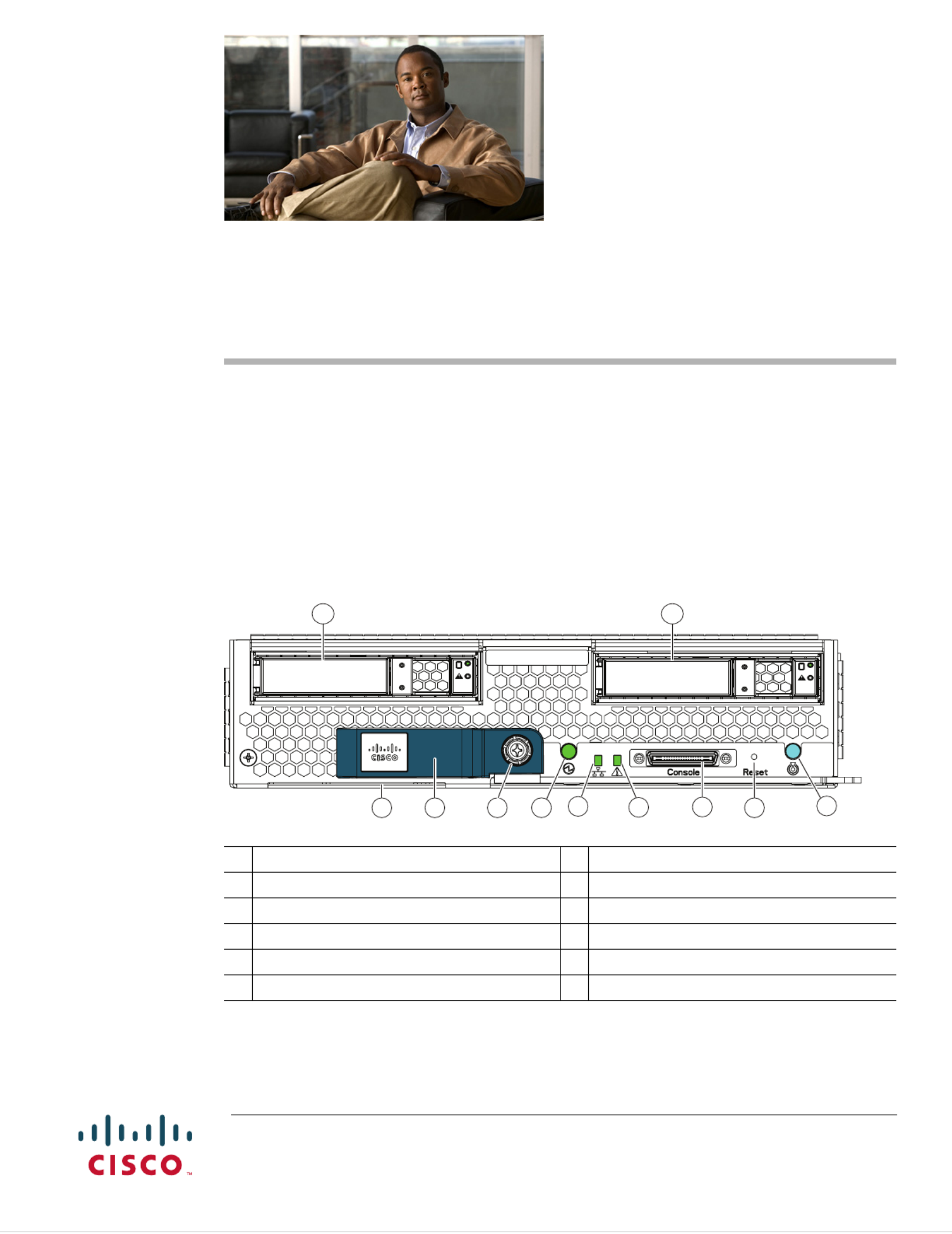
The Cisco UCS B200 M3 (shown in Figure 1) is the latest Cisco Intel-based, half-width blade supporting
two CPU sockets using Intel E5-2600 series CPUs and up to 24 DIMMs; it supports one modular LOM
(dedicated slot for Cisco's Virtual Interface Card) and one adapter card. At this time, the UCS B200 M2
(second generation) server is still available and is documented elsewhere. You can install up to eight
UCS B200 Blade Servers to a UCS chassis, mixing with other models or Cisco UCS blade servers in the
chassis if desired. The Cisco UCS B200 M3 is managed by Cisco UCS Manager version 2.0(2m) and
later.
Figure 1 Cisco UCS B200 M3 Front Panel
1 Asset tag 1
1.Each server has a blank plastic tag that pulls out of the front panel which is provided so that you can add your own
asset tracking label without interfering with the intended air flow.
7 Network link status LED
2 Blade ejector handle 8Blade health LED
3 Ejector captive screw 9Console connector
4 Hard drive bay 1 10 Reset button access
5 Hard drive bay 2 11 Beaconing LED and button
6 Power button and LED
UCS B200 M3
1 2 3 6 78 9 10 11
54
331360
2
Cisco UCS B200 M3 Blade Server Installation and Service Note
OL-26624-01
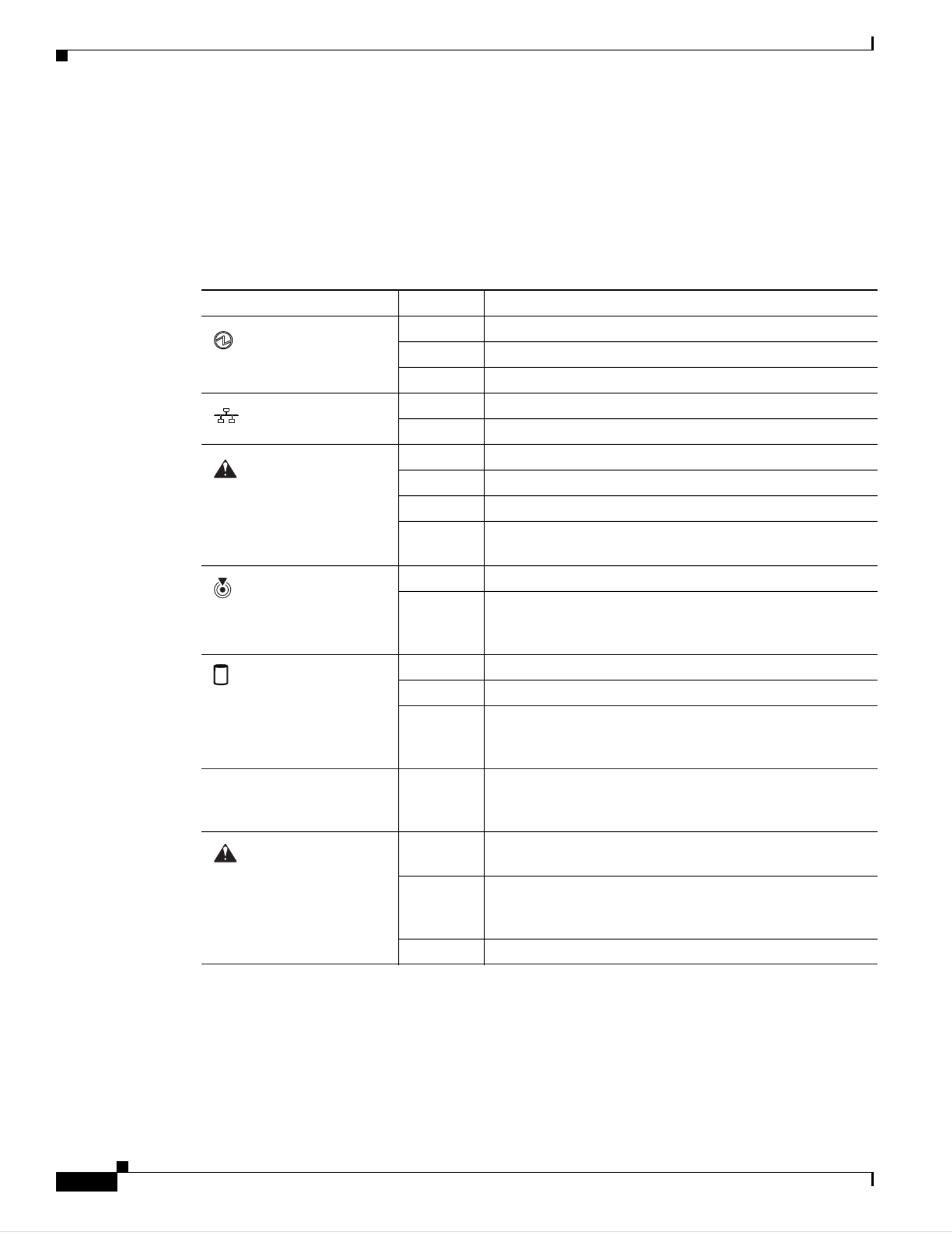
LEDs
Server LEDs indicate whether the blade server is in active or standby mode, the status of the network
link, the over all health of the blade server, and whether the server is set to give a flashing blue beaconing
indication. See Table 1 for details.
The removable hard disks also have LEDs indicating hard disk access activity and hard disk health.
Buttons
The Reset button is just inside the chassis and must be pressed using the tip of a paper clip or a similar
item. Hold the button down for five seconds, and then release it to restart the server if other methods of
restarting are not working.
Table 1 Blade Server LEDs
LED Color Description
Power Off Power off.
Green Normal operation.
Amber Standby.
Link Off None of the network links are up.
Green At least one network link is up.
Health Off Power off.
Green Normal operation.
Amber Minor error.
Blinking
Amber
Critical error.
Beaconing Off Beaconing not enabled.
Blinking
blue 1 Hz
Beaconing to locate a selected blade—If the LED is not
blinking, the blade is not selected. You can initiate
beaconing in UCS Manager or with the button.
Activity
(Disk Drive)
Off Inactive.
Green Outstanding I/O to disk drive.
Flashing
Amber
4 Hz
Rebuild in progress. Health LED will flash in unison.
Flashing
Amber
4 hz
Identify drive active.
Health
(Disk Drive)
Off Can mean either no fault detected or the drive is not
installed.
Flashing
Amber
4 hz
Identify drive active. If the Activity LED is also flashing
amber, a drive rebuild is in progress.
Amber Fault detected.
3
Cisco UCS B200 M3 Blade Server Installation and Service Note
OL-26624-01
The beaconing function for an individual server may get turned on or off by pressing the combination
button and LED. See Table 1 for details.
The power button and LED allows you to manually take a server temporarily out of service but leave it
in a state where it can be restarted quickly. If the desired power state for a service profile associated with
a blade server or an integrated rack-mount server is set to "off", using the power button or Cisco UCS
Manager to reset the server will cause the desired power state of the server to become out of sync with
the actual power state and the server may unexpected shutdown at a later time. To safely reboot a server
from a power-down state, use the Boot Server action in Cisco UCS Manager.
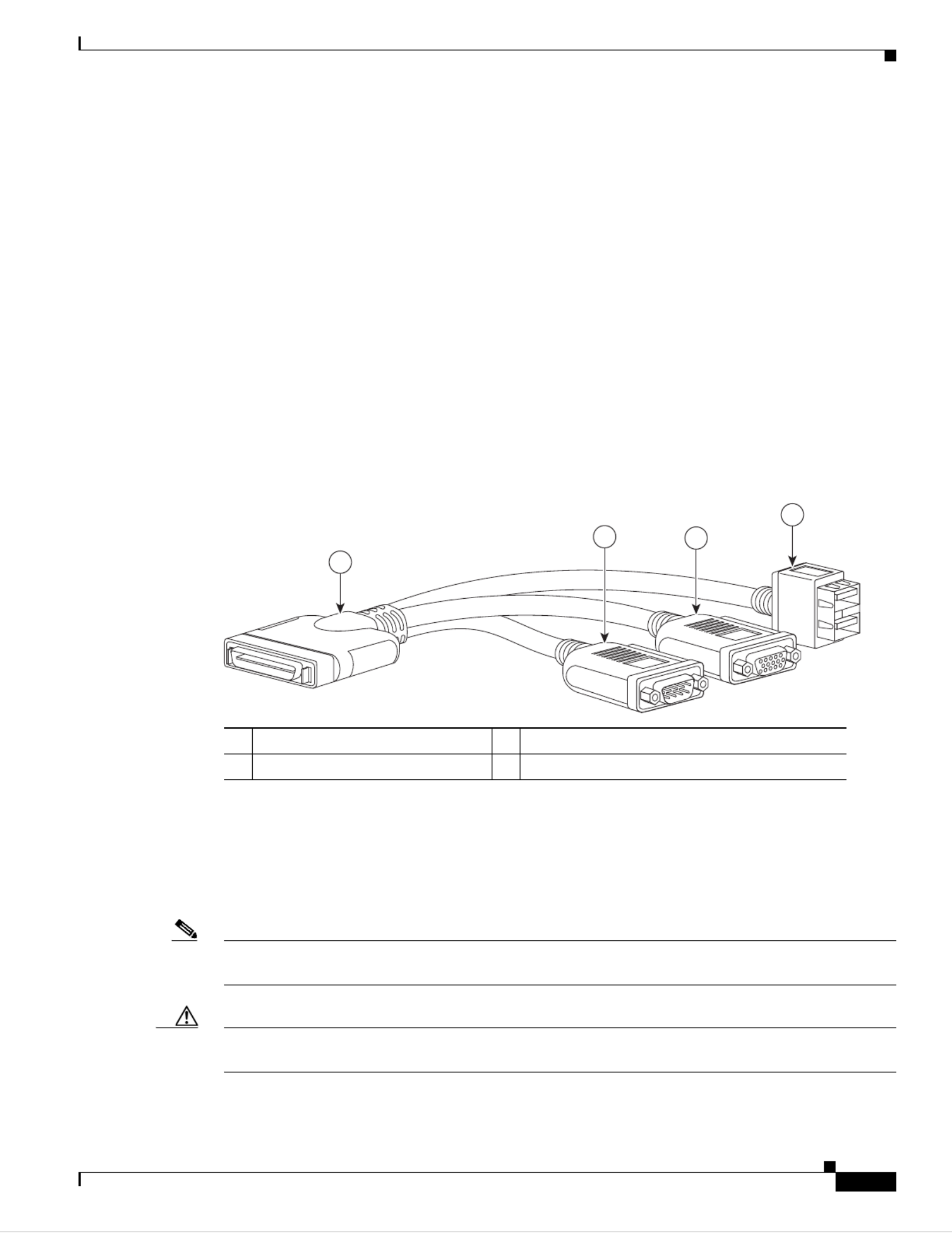
Connectors
The console port allows a direct connection to a blade server to allow operating system installation and
other management tasks to be done directly rather than remotely. The port uses the KVM dongle cable
(N20-BKVM shown in Figure 2) which provides a connection into a Cisco UCS blade server; it has a a
DB9 serial connector, a VGA connector for a monitor, and dual USB ports for a keyboard and mouse.
With this cable, you can create a direct connection to the operating system and the BIOS running on a
blade server. A KVM cable sh ade chassis accessory kit.ips standard with each bl
Figure 2 KVM Cable for Blade Servers
Conventions
This document uses the following conventions for notes, cautions, and safety warnings.
Notes and Cautions contain important information that you should know.
Note Means reader take note. Notes contain helpful suggestions or references to material that are not covered
in the publication.
Caution Means reader be careful. You are capable of doing something that might result in equipment damage or
loss of data.
1 3Connector to blade server slot VGA connection for a monitor
2 4DB9 serial connector 2-port USB connector for a mouse and keyboard
192621
1
23
4

4
Cisco UCS B200 M3 Blade Server Installation and Service Note
OL-26624-01
Safety warnings appear throughout this publication in procedures that, if performed incorrectly, can
cause physical injuries. A warning symbol precedes each warning statement.
Warning
IMPORTANT SAFETY INSTRUCTIONS
This warning symbol means danger. You are in a situation that could cause bodily injury. Before you
work on any equipment, be aware of the hazards involved with electrical circuitry and be familiar
with standard practices for preventing accidents. Use the statement number provided at the end of
each warning to locate its translation in the translated safety warnings that accompanied this
device.
Statement 1071
SAVE THESE INSTRUCTIONS
Waarschuwing
BELANGRIJKE VEILIGHEIDSINSTRUCTIES
Dit waarschuwingssymbool betekent gevaar. U verkeert in een situatie die lichamelijk letsel kan
veroorzaken. Voordat u aan enige apparatuur gaat werken, dient u zich bewust te zijn van de bij
elektrische schakelingen betrokken risico's en dient u op de hoogte te zijn van de standaard
praktijken om ongelukken te voorkomen. Gebruik het nummer van de verklaring onderaan de
waarschuwing als u een vertaling van de waarschuwing die bij het apparaat wordt geleverd, wilt
raadplegen.
BEWAAR DEZE INSTRUCTIES
Varoitus
TÄRKEITÄ TURVALLISUUSOHJEITA
Tämä varoitusmerkki merkitsee vaaraa. Tilanne voi aiheuttaa ruumiillisia vammoja. Ennen kuin
käsittelet laitteistoa, huomioi sähköpiirien käsittelemiseen liittyvät riskit ja tutustu
onnettomuuksien yleisiin ehkäisytapoihin. Turvallisuusvaroitusten käännökset löytyvät laitteen
mukana toimitettujen käännettyjen turvallisuusvaroitusten joukosta varoitusten lopussa näkyvien
lausuntonumeroiden avulla.
SÄILYTÄ NÄMÄ OHJEET
Attention
IMPORTANTES INFORMATIONS DE SÉCURITÉ
Ce symbole d'avertissement indique un danger. Vous vous trouvez dans une situation pouvant
entraîner des blessures ou des dommages corporels. Avant de travailler sur un équipement, soyez
conscient des dangers liés aux circuits électriques et familiarisez-vous avec les procédures
couramment utilisées pour éviter les accidents. Pour prendre connaissance des traductions des
avertissements figurant dans les consignes de sécurité traduites qui accompagnent cet appareil,
référez-vous au numéro de l'instruction situé à la fin de chaque avertissement.
CONSERVEZ CES INFORMATIONS

5
Cisco UCS B200 M3 Blade Server Installation and Service Note
OL-26624-01
Warnung
WICHTIGE SICHERHEITSHINWEISE
Dieses Warnsymbol bedeutet Gefahr. Sie befinden sich in einer Situation, die zu Verletzungen führen
kann. Machen Sie sich vor der Arbeit mit Geräten mit den Gefahren elektrischer Schaltungen und
den üblichen Verfahren zur Vorbeugung vor Unfällen vertraut. Suchen Sie mit der am Ende jeder
Warnung angegebenen Anweisungsnummer nach der jeweiligen Übersetzung in den übersetzten
Sicherheitshinweisen, die zusammen mit diesem Gerät ausgeliefert wurden.
BEWAHREN SIE DIESE HINWEISE GUT AUF.
Avvertenza
IMPORTANTI ISTRUZIONI SULLA SICUREZZA
Questo simbolo di avvertenza indica un pericolo. La situazione potrebbe causare infortuni alle
persone. Prima di intervenire su qualsiasi apparecchiatura, occorre essere al corrente dei pericoli
relativi ai circuiti elettrici e conoscere le procedure standard per la prevenzione di incidenti.
Utilizzare il numero di istruzione presente alla fine di ciascuna avvertenza per individuare le
traduzioni delle avvertenze riportate in questo documento.
CONSERVARE QUESTE ISTRUZIONI
Advarsel
VIKTIGE SIKKERHETSINSTRUKSJONER
Dette advarselssymbolet betyr fare. Du er i en situasjon som kan føre til skade på person. Før du
begynner å arbeide med noe av utstyret, må du være oppmerksom på farene forbundet med
elektriske kretser, og kjenne til standardprosedyrer for å forhindre ulykker. Bruk nummeret i slutten
av hver advarsel for å finne oversettelsen i de oversatte sikkerhetsadvarslene som fulgte med denne
enheten.
TA VARE PÅ DISSE INSTRUKSJONENE
Aviso
INSTRUÇÕES IMPORTANTES DE SEGURANÇA
Este símbolo de aviso significa perigo. Você está em uma situação que poderá ser causadora de
lesões corporais. Antes de iniciar a utilização de qualquer equipamento, tenha conhecimento dos
perigos envolvidos no manuseio de circuitos elétricos e familiarize-se com as práticas habituais de
prevenção de acidentes. Utilize o número da instrução fornecido ao final de cada aviso para
localizar sua tradução nos avisos de segurança traduzidos que acompanham este dispositivo.
GUARDE ESTAS INSTRUÇÕES
¡Advertencia!
INSTRUCCIONES IMPORTANTES DE SEGURIDAD
Este símbolo de aviso indica peligro. Existe riesgo para su integridad física. Antes de manipular
cualquier equipo, considere los riesgos de la corriente eléctrica y familiarícese con los
procedimientos estándar de prevención de accidentes. Al final de cada advertencia encontrará el
número que le ayudará a encontrar el texto traducido en el apartado de traducciones que acompaña
a este dispositivo.
GUARDE ESTAS INSTRUCCIONES
6
Cisco UCS B200 M3 Blade Server Installation and Service Note
OL-26624-01
Varning!
VIKTIGA SÄKERHETSANVISNINGAR
Denna varningssignal signalerar fara. Du befinner dig i en situation som kan leda till personskada.
Innan du utför arbete på någon utrustning måste du vara medveten om farorna med elkretsar och
känna till vanliga förfaranden för att förebygga olyckor. Använd det nummer som finns i slutet av
varje varning för att hitta dess översättning i de översatta säkerhetsvarningar som medföljer denna
anordning.
SPARA DESSA ANVISNINGAR

7
Cisco UCS B200 M3 Blade Server Installation and Service Note
OL-26624-01
Aviso
INSTRUÇÕES IMPORTANTES DE SEGURANÇA
Este símbolo de aviso significa perigo. Você se encontra em uma situação em que há risco de lesões
corporais. Antes de trabalhar com qualquer equipamento, esteja ciente dos riscos que envolvem os
circuitos elétricos e familiarize-se com as práticas padrão de prevenção de acidentes. Use o
número da declaração fornecido ao final de cada aviso para localizar sua tradução nos avisos de
segurança traduzidos que acompanham o dispositivo.
GUARDE ESTAS INSTRUÇÕES
Advarsel
VIGTIGE SIKKERHEDSANVISNINGER
Dette advarselssymbol betyder fare. Du befinder dig i en situation med risiko for
legemesbeskadigelse. Før du begynder arbejde på udstyr, skal du være opmærksom på de
involverede risici, der er ved elektriske kredsløb, og du skal sætte dig ind i standardprocedurer til
undgåelse af ulykker. Brug erklæringsnummeret efter hver advarsel for at finde oversættelsen i de
oversatte advarsler, der fulgte med denne enhed.
GEM DISSE ANVISNINGER
8
Cisco UCS B200 M3 Blade Server Installation and Service Note
OL-26624-01

9
Cisco UCS B200 M3 Blade Server Installation and Service Note
OL-26624-01
Installing and Removing a Blade Server Hard Drive
Installing and Removing a Blade Server Hard Drive
There are up to two front-accessible, hot-swappable, 2.5-inch drives per blade. An LSI SAS 2004 RAID
controller is embedded in the motherboard (it is not separately replaceable), and it supports RAID 0 and
1. You can remove blade server hard drives without removing the blade server from the chassis. All other
component replacements for a blade server requires removing the blade from the chassis. Unused hard
drive bays should always be covered with cover plates (N20-BBLKD) to ensure proper cooling and
ventilation. The chassis is omitted from illustrations here to simplify the drawing.
Caution To prevent ESD damage, wear grounding wrist straps during these procedures and handle modules by
the carrier edges only.
Caution RAID array migration between a B200 M1 or B200 M2 and a B200 M3 is not supported
Replacing an HDD or SSD with a drive of the same size, model, and manufacturer should not cause any
problems with UCS Manager. If the drive being replaced was part of a RAID array. we recommend using
a newly ordered drive of identical size, model, and manufacturer to replace the failed drive. We
recommend following industry standard practice of using drives of the same capacity when creating
10
Cisco UCS B200 M3 Blade Server Installation and Service Note
OL-26624-01
Installing and Removing a Blade Server Hard Drive
RAID volumes. If drives of different capacities are used, the useable portion of the smallest drive will
be used on all drives that make up the RAID volume. Before upgrading or adding an HDD to a running
system, check the service profile in UCS Manager to make sure that the new hardware configuration is
within the parameters allowed by the service profile.
Hard disk and RAID troubleshooting information is in the "Troubleshooting Server Hardware" chapter
of the Cisco UCS Troubleshooting Guide. This provides a procedure for moving a RAID array between
B200 M3 servers if needed.
The drives supported in this blade server are all hot pluggable and come with the drive sled attached.
Spare drive sleds are not available. The drives supported in this blade server are constantly being
updated. A list of currently supported and available drives is in the specification sheets at:
http://www.cisco.com/en/US/products/ps10280/products_data_sheets_list.html
Removing a Blade Server Hard Drive
To remove a hard drive from a blade server, follow these steps:
Step 1 Push the button to release the ejector, and then pull the hard drive from its slot.
Figure 3 Removing the Hard Drive
Step 2 Place the hard drive on an antistatic mat or antistatic foam if you are not immediately reinstalling it in
another server.
Step 3 Install a hard disk drive blank faceplate (N20-BBLKD) to keep dust out of the blade server if the slot
will remain empty.
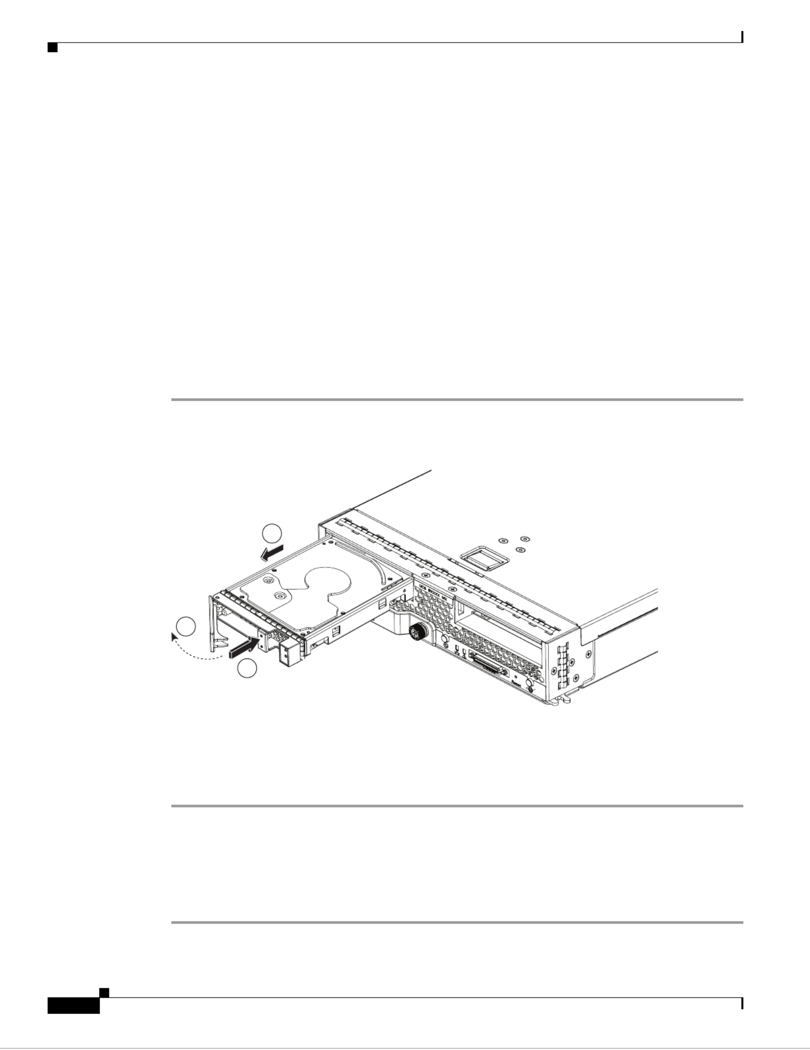
Installing a Blade Server Hard Drive
To install a blade server hard drive in a blade server, follow these steps:
Step 1 Place the hard drive lever into the open position by pushing the release button (see Figure 4).
1
2
3
331362

11
Cisco UCS B200 M3 Blade Server Installation and Service Note
OL-26624-01
Removing and Installing a UCS B200 M3 Blade Server
Figure 4 Installing a Hard Drive in a Blade Server
Step 2 Gently slide the hard drive into the opening in the blade server until it seats into place.
Step 3 Push the hard drive lever into the closed position.
You can use UCS Manager to format and configure RAID services. Refer to the UCS Manager
configuration guide for your software release for details on RAID configuration.
If you need to move a RAID cluster, refer to the Moving a RAID Cluster section of the "Troubleshooting
Server Hardware" chapter of the Cisco UCS Troubleshooting Guide.
Removing and Installing a UCS B200 M3 Blade Server
Before performing any of the following internal operations on this blade server, you must remove it from
the chassis. To prevent ESD damage, wear grounding wrist straps during these procedures and handle
modules by the carrier edges only.
Caution To prevent ESD damage, wear grounding wrist straps during these procedures and handle modules by
the carrier edges only.
Shutting Down and Powering Off a Blade Server
The server can run in two power modes:
• Main power mode—Power is supplied to all server components, and any operating system on your
hard drives can run.
• Standby power mode—Power is supplied only to the service processor and the cooling fans, and it
is safe to power off the server from this mode.
After establishing a connection to the blade server’s operating system, you can directly shut down the
blade server using the operating system.
331363
1
2

12
Cisco UCS B200 M3 Blade Server Installation and Service Note
OL-26624-01
Removing and Installing a UCS B200 M3 Blade Server
You can invoke a graceful shutdown or an emergency shutdown (hard shutdown) by using either of the
following methods:
• Use the UCS Manager. See either the Cisco UCS Manager GUI Configuration Guide or the Cisco
UCS Manager CLI Configuration Guide.
• Use the Power button on the server front panel.
To use the Power button, follow these steps:
Step 1 Check the color of the Power Status LED.
• Green indicates that the server is in main power mode and must be shut down before it can be safely
powered off. Go to Step 2.
• Amber indicates that the server is already in standby mode and can be safely powered off. Go to
Step 3.
Step 2 Invoke either a graceful shutdown or a hard shutdown:
Caution To avoid data loss or damage to your operating system, you should always invoke a graceful shutdown
of the operating system.
• Graceful shutdown—Press and release the Power button. The operating system performs a graceful
shutdown and the server goes to standby mode, which is indicated by an amber Power Status LED.
• Emergency shutdown—Press and hold the Power button for 4 seconds to force the main power off
and immediately enter standby mode.
Step 3 If you are shutting down all blade servers in a chassis, you should now disconnect the power cords from
the chassis to completely power off the servers. If you are only shutting down one server, you can skip
unplugging the chassis and move to removing the server.
Removing a Cisco UCS B200 M3 Blade Server
Using UCS Manager, decommission the server before physically removing the server. To remove a blade
server from the chassis, follow these steps:
Step 1 Loosen the captive screw on the front of the blade.
Step 2 Remove the blade from the chassis by pulling the ejector lever on the blade until it unseats the blade
server.
Step 3 Slide the blade part of the way out of the chassis, and place your other hand under the blade to support
its weight.
Step 4 Once removed, place the blade on an antistatic mat or antistatic foam if you are not immediately
reinstalling it into another slot.
Step 5 If the slot is to remain empty, install a blank faceplate (N20-CBLKB1) to keep dust out of the chassis.

13
Cisco UCS B200 M3 Blade Server Installation and Service Note
OL-26624-01
Removing and Installing a UCS B200 M3 Blade Server
Installing a Cisco UCS B200 M3 Blade Server
UCS B200 M3 blade servers are interoperable in a UCS chassis with any other UCS blade servers,
including prior generation B200 M2 and B200 M1 servers, or other UCS B-Series blade servers. To
install a blade server, follow these steps:
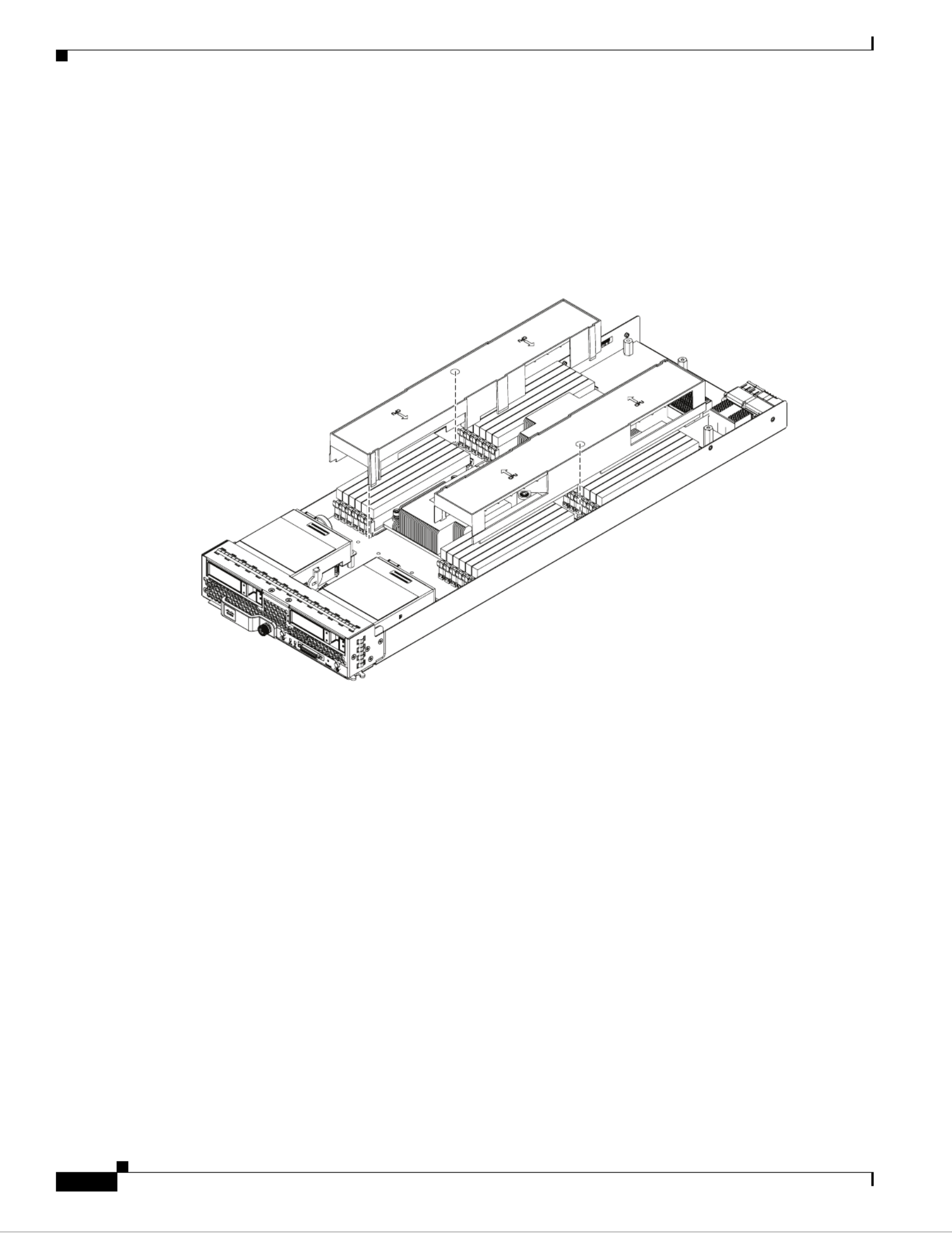
Step 1 Grasp the front of the blade server and place your other hand under the blade to support it. See Figure 5.
Figure 5 Positioning a Blade Server in the Chassis
Step 2 Open the ejector lever in the front of the blade server.
Step 3 Gently slide the blade into the opening until you cannot push it any farther.
Step 4 Press the ejector lever so that it catches the edge of the chassis and presses the blade server all the way in.
Step 5 Tighten the captive screw on the front of the blade to no more than 3 in-lbs. Tightening with bare fingers
only is unlikely to lead to stripped or damaged captive screws.
Step 6 Power on the server. UCS Manager automatically reacknowledges, reassociates, and recommissions the
server, provided any hardware changes are allowed by the service profile.
331364

14
Cisco UCS B200 M3 Blade Server Installation and Service Note
OL-26624-01
Secure Digital (SD) Card Access
Figure 5 shows the positioning of a blade server in the chassis. Blade servers reside within the eight
upper slots of the chassis.
Secure Digital (SD) Card Access
SD card slots are provided for future usage. Their use is not supported at product release. They will
require a future software update to be used.
Figure 6 SD Card Slot Locations
332219

15
Cisco UCS B200 M3 Blade Server Installation and Service Note
OL-26624-01
Removing a Blade Server Cover
Removing a Blade Server Cover
To open a blade server, follow these steps:
Step 1 Press and hold the button down as shown in Figure 7.
Step 2 While holding the back end of the cover, pull the cover up and back.
Figure 7 Opening a Cisco UCS B200 M3 Blade Server
331365
1
2
16
Cisco UCS B200 M3 Blade Server Installation and Service Note
OL-26624-01
Removing a Blade Server Cover
Air Baffles
The air baffles (shown in Figure 8) direct and improve air flow for the server components. Two identical
baffles ship with each B200 M3 server. No tools are necessary to install them, just place them over the
DIMMs as shown, with the holes in the center of the baffles aligned with the corresponding motherboard
standoffs.
Figure 8 Cisco UCS B200 M3 Air Baffles
33 31 66
17
Cisco UCS B200 M3 Blade Server Installation and Service Note
OL-26624-01
Removing a Blade Server Cover
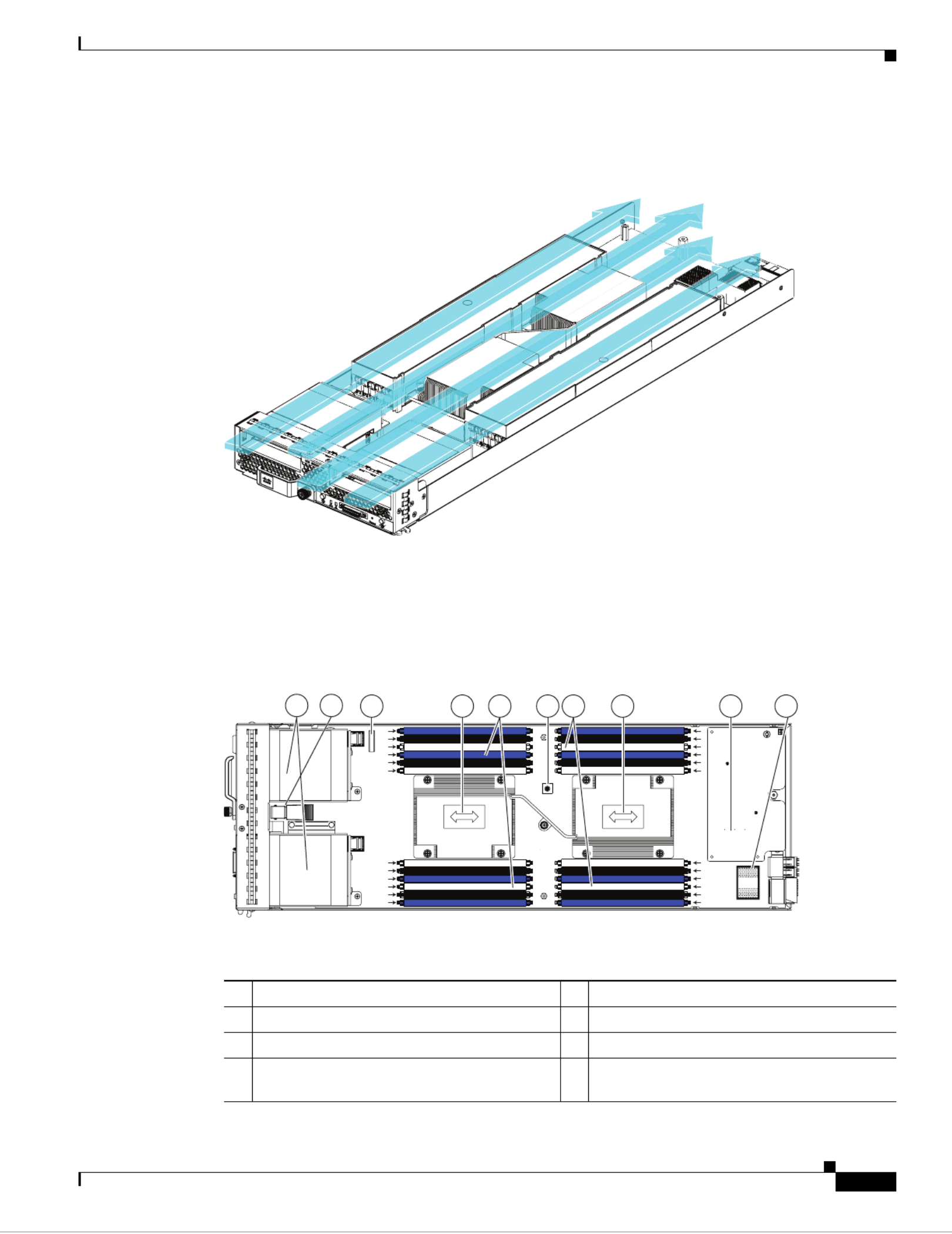
Once installed, the air baffles direct the intake air into four distinct lanes as shown in Figure 9.
Figure 9 Cisco UCS B200 M3 Air Flow
Internal Components
Figure 10 calls out the various components within the blade server.
Figure 10 Inside View of a Blade Server
33 317 1
1 2Hard drive bays Internal USB connector
1
3 4Battery CPU and heat sink
5 6DIMM slots Diagnostic button
7 Modular LOM (shown installed) 8Adapter card connector
(Adapter not shown installed)
CPU 1
CPU 2
C0
C1
C2
D0
D1
D2
B2
B1
B0
A2
A1
A0
E0
E0
E0
E0
E0E0
E1
E1
E1
E1
E1E1
E2
E2
E2
E2
E2E2
F0
F0
F0
F0
F0F0
F1
F1
F1
F1
F1F1
F2
F2
F2
F2
F2F2
E0
E1
E2
F0
F1
F2
H2
H1
H0
G2
G1
G0
1 2 3 4 4 7 85 6 5
331367

18
Cisco UCS B200 M3 Blade Server Installation and Service Note
OL-26624-01
Working Inside the Blade Server
Note Use of this server may require an upgrade to the IOM in the chassis. This server only supports third
generation adapter cards, which have features requiring a Cisco 2204 or 2208 IOM, and are not
backward compatible with the Cisco 2104 IOM.
Diagnostics Button and LEDs
At blade start-up, Power-on Self Test (POST) diagnostics test the CPUs, DIMMs, HDDs and adapter
cards. Any failure notifications are sent to Cisco Ucs Manager. You can view these notification in the
System Error Log or in the output of the show tech-support command. If errors are found, an amber
diagnostic LED also lights up next to the failed component. During run time, the blade BIOS, component
drivers, and OS all monitor for hardware faults and the amber diagnostic LED for a component lights up
if an uncorrectable error or correctable errors (such as a host ECC error) over the allowed threshold
occur.
LED states are saved. If you remove the blade from the chassis, the LED values are preserved in memory
for up to 10 minutes. Pressing the LED diagnostics button on the motherboard causes the LEDs that
currently show a component fault to light for up to 30 seconds for easier component identification. LED
fault values are reset when the blade is reinserted into the chassis and booted, and the process begins
again.
If DIMM insertion errors are detected, they may cause the blade discovery to fail and errors will be
reported in the server POST information, viewable using the UCS Manager GUI or CLI. Cisco UCS
blade servers require specific rules to be followed when populating DIMMs in a blade server, and the
rules depend on the blade server model. Refer to the section on DIMM population for those rules.
Drive status LEDs are on the front face of the drive. Faults on the CPU, DIMMs, or adapter cards also
cause the server health LED to light solid amber for minor error conditions or blinking amber for critical
error conditions.
Working Inside the Blade Server
This section describes how to perform the following tasks within a blade server:
•Installing a Motherboard CMOS Battery, page 19
•Removing and Installing a CPU and Heat Sink, page 20
•Installing Memory, page 27
•Installing an Adapter Card, page 33
1. Cisco UCS-USBFLSH-S-4GB= is recommended, but if another USB drive will be used it must be no wider than .8 inches,
and no more than 1.345 inches long in order tp provide needed clearances to install or remove the USB drive.

19
Cisco UCS B200 M3 Blade Server Installation and Service Note
OL-26624-01
Working Inside the Blade Server
Installing a Motherboard CMOS Battery
This server supports the CR2032 CMOS battery (N20-MBLIBATT).
Warning
There is danger of explosion if the battery is replaced incorrectly. Replace the battery only with the
same or equivalent type recommended by the manufacturer. Dispose of used batteries according to
the manufacturer’s instructions.
Statement 1015
To install or replace a motherboard complementary metal-oxide semiconductor (CMOS) battery, follow
these steps:
Step 1 Remove a motherboard CMOS battery:
a. Power off the blade, remove it from the chassis, and remove the top cover as described in the
“Removing a Blade Server Cover” section on page 15.
b. Press the battery socket retaining clip toward the chassis wall (see Figure 11).
c. Lift the battery from the socket. Use needle-nose pliers to grasp the battery if there is not enough
clearance for your fingers.
Step 2 Install a motherboard CMOS battery:
a. Press the battery socket retaining clip toward the chassis wall.
b. Insert the new battery into the socket with the battery’s negative (–) marking toward the chassis wall.
Ensure that the retaining clip clicks over the top of the battery.
c. Replace the top cover.
d. Replace the server in the chassis and power on the blade by pressing the Power button.
21
Cisco UCS B200 M3 Blade Server Installation and Service Note
OL-26624-01
Working Inside the Blade Server
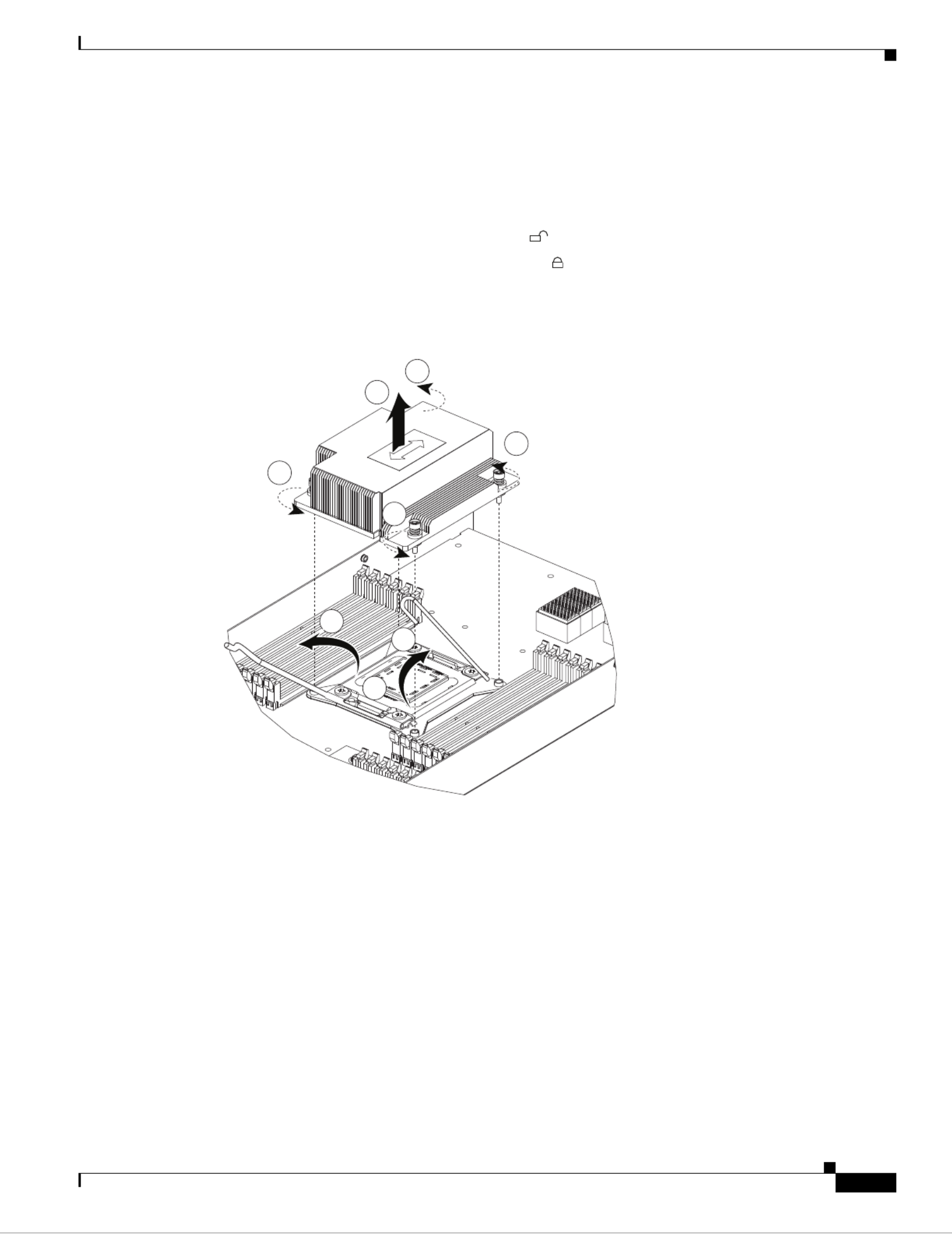
Loosen one screw by a quarter turn, then move to the next in the X pattern shown in Figure 17 on
page 26. Continue loosening until the heat sink can be lifted off.
Step 2 Remove the heat sink. See Figure 12, callout 2. Remove the existing thermal compound from the bottom
of the heat sink using the cleaning kit (UCSX-HSCK= ) included with each CPU option kit. Follow the
instructions on the two bottles of cleaning solvent.
Step 3 Unhook the first socket hook, marked with an icon. See Figure 12, callout 3.
Step 4 Unhook the second socket hook, marked with an icon. See Figure 12, callout 4.
Step 5 Open the socket latch. See Figure 12, callout 5.
Figure 12 Removing the Heat Sink and Accessing the CPU Socket (UCS B200 M3 Server Shown)
Step 6 Press the central button on the provided CPU pick and place tool (UCS-CPU-EP-PNP=) to release the
catch. See Figure 13.
The CPU pick and place tool is included with each CPU option kit, or the tool may be purchased
separately. Be sure to use the tool for the Intel Xeon E5-2600 Series processors.
Step 7 Remove an old CPU as follows:
a. Place the CPU pick and place tool on the CPU socket aligned with the arrow pointing to the CPU
registration mark as shown in Figure 13.
b. Press the button/handle on the tool to grasp the installed CPU.
c. Lift the tool and CPU straight up.
331369
1
2
1
1
1
3
5
4
Termékspecifikációk
| Márka: | Cisco |
| Kategória: | szerver |
| Modell: | UCS B200 M3 |
Szüksége van segítségre?
Ha segítségre van szüksége Cisco UCS B200 M3, tegyen fel kérdést alább, és más felhasználók válaszolnak Önnek
Útmutatók szerver Cisco

12 Augusztus 2024
2 Augusztus 2024
31 Július 2024
30 Július 2024
28 Július 2024
25 Július 2024
23 Július 2024
20 Július 2024
16 Július 2024
15 Július 2024
Útmutatók szerver
- szerver Sony
- szerver Fujitsu
- szerver Acer
- szerver StarTech.com
- szerver Lenovo
- szerver Toshiba
- szerver HP
- szerver Medion
- szerver Vimar
- szerver Technics
- szerver Rocstor
- szerver Digitus
- szerver TRENDnet
- szerver Dell
- szerver Gigabyte
- szerver Tripp Lite
- szerver Conceptronic
- szerver Blackmagic Design
- szerver Hikvision
- szerver Netgear
- szerver Asus
- szerver ELAC
- szerver Synology
- szerver Supermicro
- szerver ZyXEL
- szerver Smart-AVI
- szerver Planet
- szerver Ernitec
- szerver Black Box
- szerver MSI
- szerver ATen
- szerver APC
- szerver SEH
- szerver Western Digital
- szerver HGST
- szerver D-Link
- szerver Monacor
- szerver Moxa
- szerver Abus
- szerver Veritas
- szerver Atlona
- szerver Lindy
- szerver Areca
- szerver QNAP
- szerver NEC
- szerver Siig
- szerver Eaton
- szerver Gefen
- szerver Kathrein
- szerver IStarUSA
- szerver Lantronix
- szerver Provision-ISR
- szerver Axis
- szerver NETSCOUT
- szerver Sitecom
- szerver ACTi
- szerver Megasat
- szerver KanexPro
- szerver Kramer
- szerver Allnet
- szerver SilverStone
- szerver Maxdata
- szerver AVerMedia
- szerver Matrox
- szerver Flir
- szerver Buffalo
- szerver GeoVision
- szerver LevelOne
- szerver LaCie
- szerver Valcom
- szerver Asustor
- szerver Intel
- szerver Fantec
- szerver Freecom
- szerver Seagate
- szerver Iomega
- szerver Digi
- szerver Revox
- szerver Luxman
- szerver Ibm
- szerver Sonnet
- szerver TAIDEN
- szerver Advantech
- szerver Extron
- szerver Avocent
- szerver Intellinet
- szerver Teradek
- szerver Silex
- szerver Hanwha
- szerver In Win
- szerver Sun
- szerver MvixUSA
- szerver Dual Bay
- szerver Raidsonic
- szerver EMC
- szerver Infortrend
- szerver Opengear
- szerver G-Technology
- szerver EXSYS
- szerver Chenbro Micom
- szerver Middle Atlantic
- szerver Mr. Signal
- szerver Atlantis Land
- szerver C2G
- szerver Promise Technology
- szerver Mobotix
- szerver Origin Storage
Legújabb útmutatók szerver

9 Április 2025
3 Április 2025

2 Április 2025
29 Március 2025
29 Március 2025
29 Március 2025
24 Március 2025
24 Március 2025

15 Január 2025
15 Január 2025