Használati útmutató Casio IT-800
Olvassa el alább 📖 a magyar nyelvű használati útmutatót Casio IT-800 (73 oldal) a Doboz kategóriában. Ezt az útmutatót 8 ember találta hasznosnak és 2 felhasználó értékelte átlagosan 4.5 csillagra
Oldal 1/73
Handheld Terminal
User’s Guide
Series
Be sure to read “Safety
Precautions” inside this
guide before trying to use
your Handheld Terminal.
E

E-1
Contents
Safety Precautions ........................................................................................E-3
Operating Precautions ..................................................................................E-8
Important ........................................................................................................E-8
After Service ........................................................................................................E-8
Regulatory Information .................................................................................E-9
Checking in the Box ....................................................................................E-13
Handheld Terminal System Confi guration ................................................E-14
General Guide ...............................................................................................E-16
Loading and Removing the Battery Pack ..................................................E-19
Loading ..............................................................................................................E-20
Removing ........................................................................................................... E-21
Charging the Battery Pack .........................................................................E-22
USB Cradle/Ethernet Cradle/Cradle-type Battery Charger ...............................E-22
Car Mounted-type Battery Charger ....................................................................E-22
Dual Battery Charger .........................................................................................E-23
AC Adaptor ........................................................................................................E-23
Handling the Hand Belt ...............................................................................E-24
To remove the hand belt .....................................................................................E-24
To attach the hand belt ......................................................................................E-24
Connecting the Stylus String .......................................................................E-25
Attaching the Neck Strap ............................................................................E-26
To attach the neck strap ...................................................................................... E-26
Confi guring Handheld Terminal Settings ..................................................E-27
Calibrating Touch Screen Alignment ................................................................. E-27
Adjusting Display Brightness ............................................................................E-28
Display Auto Dimmer ........................................................................................E-28
Using the Laser Scanner (Laser Models) ..................................................E-29
Using the C-MOS Imager (Imager Models) ................................................E-30
Adjusting the Laser Light Emission Width ................................................E-31
Handling the NFC ........................................................................................E-33
Performing Communications .....................................................................E-34
IR Communication ............................................................................................. E-34
Bluetooth® Communication ............................................................................... E-35
GSM/W-CDMA Communication ......................................................................E-36
GPS .................................................................................................................... E-36

E-2
Handling microSD Cards ............................................................................E-37
Installing.............................................................................................................E-37
Removing ........................................................................................................... E-38
Handling SIM Cards .....................................................................................E-39
Installing.............................................................................................................E-39
Removing ........................................................................................................... E-40
Handling SD Memory Cards .......................................................................E-41
Installing.............................................................................................................E-41
Removing ........................................................................................................... E-41
Resetting the Handheld Terminal ...............................................................E-42
Performing a Full Reset (Initialization) .............................................................E-42
Warning Label ..............................................................................................E-44
IT-800 Specifi cations ...................................................................................E-45
Using the USB Cradle (HA-H60IO) ..............................................................E-49
General Guide ........................................................................................................49
Connecting the USB Cradle Power Supply ...........................................................51
Specifi cations .........................................................................................................54
Using the Ethernet Cradle (HA-H62IO) .......................................................E-55
General Guide ........................................................................................................55
Connecting the Ethernet Cradle Power Supply ......................................................57
Specifi cations .........................................................................................................59
Using the Cradle-type Battery Charger (HA-H30CHG) .............................E-60
General Guide ........................................................................................................60
Connecting the Cradle-type Battery Charger Power Supply .................................61
Specifi cations .........................................................................................................62
Using the Car Mounted-type Battery Charger (HA-H35CHG) ..................E-63
General Guide ........................................................................................................63
Specifi cations .........................................................................................................64
Using the Dual Battery Charger (HA-D32DCHG) .......................................E-65
General Guide ........................................................................................................65
Charging a Battery Pack.........................................................................................67
Connecting Multiple Dual Battery Chargers..........................................................68
Specifi cations .........................................................................................................69
Using the AC Adaptor (AD-S15050B) ..........................................................E-70
Using Rechargeable Battery Packs ............................................................E-71
Battery Pack Specifi cations ....................................................................................71
Large-capacity Battery Pack Specifi cations ...........................................................71
E-3
Safety Precautions
Congratulations upon your selection of this CASIO product. Be sure to read the
following Safety Precautions before trying to use it for the fi rst time.
Your neglect or avoidance of the warning and caution statements in the
subsequent pages causes the danger of fi re, electric shock, malfunction and
damage on the goods as well as personal injury.
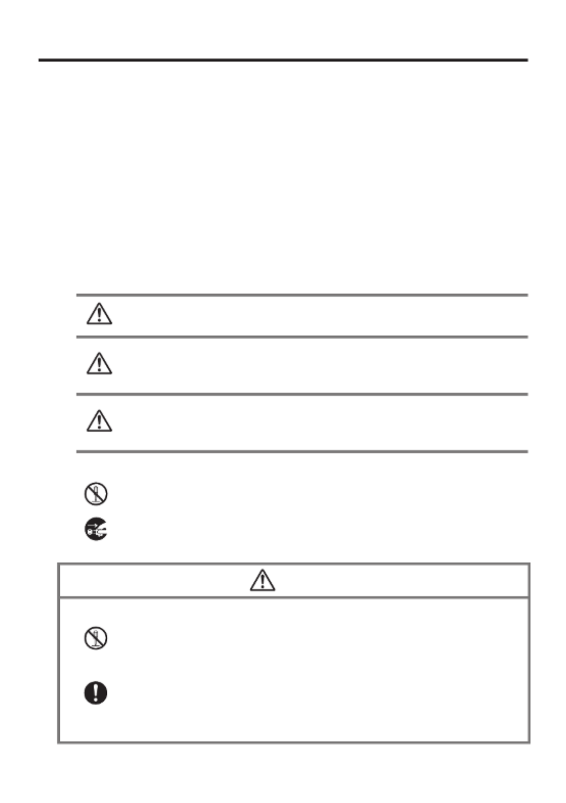
Markings and Symbols
The following are the meanings of the markings and symbols used in these Safety
Precautions.
Danger This symbol indicates information that, if ignored or applied
incorrectly, creates the danger of death or serious personal injury.
Warning
This symbol indicates information that, if ignored or applied
incorrectly, creates the possibility of death or serious personal
injury.
Caution
This symbol indicates information that, if ignored or applied
incorrectly, creates the possibility of personal injury or property
damage.
A diagonal line indicates something you should not do. The symbol shown
here indicates you should not try to take the unit apart.
A black circle indicates something you should do. The symbol shown here
indicates you should unplug the unit from the wall outlet.
Warning
Disassembly and Modifi cation
Never try to disassemble or modify the Handheld Terminal and its options
including battery pack and battery in any way.
Abnormal Conditions
Should the Handheld Terminal and/or its options including battery pack and
battery become hot or start to emit smoke or a strange odor, immediately turn
off the power and contact your dealer or distributor whom you purchased the
product from, or an authorized CASIO service provider.
•
•
•
•

E-4
Warning
Dust and Moisture
Though the Handheld Terminal is dust and water splash resistant, its options
including the battery pack are not. Keep loose metal objects and containers
fi lled with liquid away from your Handheld Terminal and the options. Also,
never handle the Handheld Terminal and the options while your hands are
wet.
Laser Light
The laser scanner models (model dependant) with the integrated laser
scanning module scan bar codes using laser light. Never look directly into
the laser light or shine the laser light into the eyes.
•
•
Warning
Interference with the Operation of Other Equipment
(Using Wireless Data Communication)
Keep your Handheld Terminal at least 22 centimeters (8
11/16") away from
anyone wearing a pacemaker. Radio waves emitted by the Handheld
Terminal can affect the operation of a pacemaker.
Before the use in aircraft, be sure to consult with cabin crew for interference
the Handheld Terminal emits.
Before the use in medical facility, be sure to consult with the facility
management or the manufacture of a specifi c medical equipment that the
Handheld Terminal may interfere with.
Do not use the Handheld Terminal nearby gas pump or chemical tank or any
other places fl ammable or explosive.
To comply with the relevant European RF exposure compliance
requirements, a separation distance of at least 3.8cm in wireless operation
must be maintained between the terminal and all persons around. This
terminal must not be co-located or operating in conjunction with other
transmitter.
•
•
•
•
•

E-5
Caution
Foreign Objects
Take care to ensure that metals or combustible objects are not inserted into
the openings of the Handheld Terminal or its options, and not to allow
moisture to get inside of them.
Location
Install the cradle properly on a fl at and stable surface so that it cannot fall
down onto fl oor.
LCD Screen
Never apply strong pressure to the screen or subject it to strong impact.
Doing so can crack the LCD Screen.
•
•
•
Warning
Avoiding Traffi c Accidents
Never use your Car Mounted-type Battery Charger while operating a motor
vehicle. Park your vehicle in a safe place before performing any operation.
Never locate the Car Mounted-type Battery Charger where it might interfere
with proper operation of the vehicle.
Locate connecting cables as instructed by the manual, avoiding locations
that can interfere with driving operations.
Car Battery Power
Should the Car Power Cable become damaged, replace it immediately with
a new Car Power Cable when using the Car Mounted-type Battery Charger.
•
•
•
•
Caution
Installing in Vehicle
To save your vehicle’s battery from running down, be sure that the Car
Power Cable should be unplugged from the cigarette lighter socket when
you do not use the Car Mounted-type Battery Charger and that the use of
the battery charger should be avoid while the vehicle’s engine is turned off.
Do not handle the Car Power Cable with wet hands.
Install the Car Mounted-type Battery Charger at location in a vehicle where
strong vibration, unstable, excessive of humidity and dust, and under direct
sunlight can be avoid. Also, avoid the area where the air bag infl ates or any
other area where your safe driving is blocked.
Do not leave the Handheld Terminal in vehicle for a long period of time.
•
•
•
•

E-6
Optional Lithium-ion Battery Pack
Danger
Never use the Handheld Terminal and its option including the battery pack
and battery next to open fl ame, near a stove, or any other area exposed to
high heat, or leave them for a long period of time in a vehicle parked in
direct sunlight.
Never use the battery pack with any device other than the Handheld
Terminal.
Never dispose of the battery pack by incinerating it or otherwise expose it
to heat.
Never transport or store the battery pack together with metal objects that
may result in shorting positive (+) and negative (–) terminals of the battery
pack. Be sure to place the battery pack in its case whenever transporting or
storing it.
Never throw the battery pack or otherwise subject it to strong impact.
Never pierce the battery pack with nails, hit it with a hammer, or step on it.
Use only the specifi ed battery charger to charge the battery pack.
•
•
•
•
•
•
•
Warning
Never place the battery pack in a microwave oven or any other high-voltage
device.
If the amount of time period the battery pack can serve becomes
considerably short even after it has been fully charged for the specifi ed time
period, stop using it.
Should the battery pack start to leak or emit a strange odor, immediately
move it away from any fl ame nearby. Leaking battery fl uid is combustible.
Should fl uid from the battery pack accidentally get into your eyes or on the
skin, do not rub it. Immediately rinse it off with clean tap water and then
consult a physician.
•
•
•
•
Caution
Replace only with the same type of battery pack recommended by CASIO.
Dispose of used battery packs according to the local regulation.
Keep the battery pack out of the reach of small children.
•
•

E-7
Power Supply / AC Adaptor
Warning
Do not use the Handheld Terminal at a voltage other than the specifi ed
voltage. Also, do not connect the Handheld Terminal to a multi-plug power
strip.
Never modify, sharply bend, twist, or pull on the power cord.
Never use a detergent to clean AC adaptor and its power cable, especially
on the plug and the jack.
When using the battery chargers and the cradles, be sure to use the
respective AC adaptors.
•
•
•
•
Caution
Never pull on the power cord when unplugging it. Always hold the plug
when unplugging it from the wall outlet.
Never touch the plug while your hands are wet.
Be sure to unplug the power cord from the wall outlet before cleaning the
battery chargers and the cradles.
Unplug the power cord from the wall outlet whenever leaving the battery
chargers and the cradles unattended for a long period.
The housing of the AC adaptor can become warm during normal use.
At least once a year, unplug the AC adaptor from the wall outlet and clean
any dust that builds up between the prongs of the plug.
Dust built up between the prongs can lead to the danger of fi re.
•
•
•
•
•
•
Backup of All Important Data
Caution
Note that CASIO Computer Co., Ltd. shall not be held liable to you or any
third party for any damages or loss caused by deletion or corruption of data
due to use of the Handheld Terminal, malfunction or repair of the Handheld
Terminal or its peripherals, or due to the batteries going dead.
The Handheld Terminal employs electronic memory to store data, which
means that memory contents can be corrupted or deleted if power is
interrupted due to the batteries going dead or incorrect battery replacement
procedures. Data cannot be recovered once it is lost or corrupted. Be sure
to make backup of all important data. One way to do this is to use the
separately sold cradles to transfer data to a computer.
•
•

E-8
Operating Precautions
Your Handheld Terminal and its options are precision. Improper operation or rough
handling can cause problems with data storage and other problems. Note and observe
the following precautions to ensure proper operation.
Do not leave dead battery pack in the Handheld Terminal for a long period.
Dead battery pack can leak, leading to malfunction and damage to the Handheld
Terminal.
Stop or avoid using the Handheld Terminal and its options in areas and
conditions subject to the following.
— Large amounts of static electricity
— Extreme heat or cold or humidity
— Sudden temperature change
— Large amount of dust
— After large amount of rain or water falls on the Handheld Terminal
— Pressing the screen or keys with excessive force when using in the rain
Dead Pixels
The LCD panel employed in this product uses high precision and substantial number
of components which commonly cause a small number of the pixels not to light or
to remain lit all the time. This is due to the characteristics of LCD panel yield in
accuracy over 99.99% and permissible.
802.11a Restrictions (IT-800A-35):
— This product is for indoor use only when using channels 36, 40, 44, 48, 52, 56, 60,
or 64 (5150-5350 MHz).
— To ensure compliance with local regulations, be sure to select the country in which
the access point is installed.
Important
This guide does not include any information about programming and download
procedures. See the applicable separate documentation for information about the
procedures.
After Service
Should this product ever malfunction, contact your original retailer providing
information about the product name, the date you purchased it, and details about the
problem.
This mark applies to EU countries and Turkey only.
•
•
•
•
•
•

E-9
Regulatory Information
The USA and Canada
The CASIO IT-800 models are designed, tested and found to meet the relevant regulatory
standards described below.
USA
IT-800E
FCC Part 15 Subpart B
FCC Part 15 Subpart C
SAR ET DOCKET 93-62 and OET BULLETIN
CFR 21 Subpart 1000 (FDA)
UL 60950-1
HA-H60IO/HA-H62IO/HA-H30CHG
FCC Part 15 Subpart B
UL 60950-1
Canada
IT-800E
RSS-GEN
RSS-210
RSS-102
RSS-310
ICES-003
cUL 60950-1
HA-H60IO/HA-H62IO/HA-H30CHG
ICES-003
cUL 60950-1

E-10
GUIDELINES LAID DOWN BY FCC RULES FOR USE OF THIS UNIT IN THE U.S.A. (not
applicable to other areas).
NOTICE
This equipment has been tested and found to comply with the limits for a Class B digital device, pursuant
to Part 15 of the FCC Rules. These limits are designed to provide reasonable protection against harmful
interference in a residential installation. This equipment generates, uses and can radiate radio frequency
energy and, if not installed and used in accordance with the instructions, may cause harmful interference
to radio communications. However, there is no guarantee that interference will not occur in a particular
installation. If this equipment does cause harmful interference to radio or television reception, which can
be determined by turning the equipment off and on, the user is encouraged to try to correct the interference
by one or more of the following measures:
Reorient or relocate the receiving antenna.
Increase the separation between the equipment and receiver.
Connect the equipment into an outlet on a circuit different from that to which the receiver is connected.
Consult the dealer or an experienced radio/TV technician for help.
FCC WARNING
Changes or modifi cations not expressly approved by the party responsible for compliance could void
the user’s authority to operate the equipment.
Proper connectors must be used for connection to host computer and/or peripherals in order to meet FCC
emission limits.
Caution Exposure to radio frequency radiation (below is for portable device)
To comply with FCC RF exposure compliance requirements, this device must not be co-located or
operating in conjunction with any other antenna or transmitter.
•
•
•
•
Declaration of Conformity
Model Number: HA-H60IO, HA-H62IO
Trade Name: CASIO
Responsible party: Industrial Handheld Division
Casio America, Inc.
Address: 570 Mt. Pleasant Avenue, Dover, New Jersey 07801, USA
Telephone number: 973-361-5400
This device complies with Part 15 of the FCC Rules. Operation is subject to the following two conditions:
(1) This device may not cause harmful interference, and (2) this device must accept any interference
received, including interference that may cause undesired operation.
For Users in Canada
These Class B digital apparatuses comply with Canadian ICES-003.
Cet appareil numériqué de la classes B est conformé à la norme NMB-003 du Canada.
These devices comply with RSS 210 of Industry Canada (IC).
Operation is subject to the following two conditions:
(1) These devices may not cause interference, and
(2) These devices must accept any interference, including interference that may cause undesired opera-
tion of this device.
E-11
L’ utilisation de ce dispositif est autorisée seulement aux conditions suivantes :
(1) il ne doit pas produire de brouillage et
(2) I’ utilisateur du dispositif doit étre prêt à accepter tout brouillage radioélectrique reçu, même si ce
brouillage est susceptible de compromettre le fonctionnement du dispositif.
Exposure to radio frequency radiation
The installer of this radio equipment must ensure that the antenna is located or pointed such that it does
not emit RF fi eld in excess of Health Canada limits for the general population;
consult Safety Code 6, obtainable from Health Canada's website at
http://www.hc-sc.gc.ca/ewh-semt/pubs/radiation/99ehd-dhm237/index_e.html
Europe
Products are for distribution within
all member states of the EU.
France limited to 2446.5-2483.5 MHz Indoor use.
Belgium limited to 2400-2483.5 MHz Indoor, 2460-2483.5 MHz Outdoor use.
0984
0984
0984
0984
0984
Optional models HA-H60IO, HA-H62IO, HA-H30CHG, HA-H35CHG, HA-D32DCHG, HA-
D20BAT and HA-D21LBAT are in conformity with the Council Directive 2004/108/EC.
Manufacturer:
CASIO COMPUTER CO., LTD.
6-2, Hon-machi 1-chome, Shibuya-ku, Tokyo 151-8543, Japan
Representative within the European Union:
CASIO EUROPE GmbH
Casio-Platz 1, 22848 Norderstedt, Germany

E-12
DECLARATION OF CONFORMITY
We, the under signed, CASIO Europe GmbH, hereby declare that the following types of the
product:
Product: Handheld Terminal
Type: IT-800R, IT-800RG
Brand: CASIO
are in conformity with all the provisions of the EC directive bellow meeting with the
relevant standards:
Council Directive: 1999/5/EC (R&TTE Directive):
Standards applied to all the types:
EN 300 328 v1.7.1 (2006-10) EN 60950-1: 2006
EN 300 330-2 v1.3.1 (2006-04) EN 50364: 2001
EN 301 489-3 v1.4.1 EN 62311: 2008
EN 301 489-17 v2.1.1
Standards applied to IT-800RG only:
EN 301 511 v9.0.2 EN 301 489-1 v1.8.1
EN 301 908-1 v3.2.1 EN 301 489-7 v1.3.1
EN 301 908-2 v3.2.1 EN 301 489-24 v1.4.1
EN 50360: 2001
These types of the product are fully compliant with all the essential requirements of the
directive and the standards that are assessed by the following Notifi ed Body.
Compliance Certifi cation Services (NB Number; 0984).
Manufacturer:
CASIO COMPUTER CO., LTD.
6-2, Hon-machi 1-chome, Shibuya-ku, Tokyo 151-8543, Japan
Representative within the European Union:
CASIO Europe GmbH
Casio-Platz 1, 22848 Norderstedt, Germany

E-13
Checking in the Box
Please check the contents of the box before using the Handheld Terminal for the fi rst
time.
Open the box and make sure that all the items shown here are included.
The stylus string can be
attached to the stylus
and hand belt.
User's Guide (this manual)
Handheld Terminal Neck Strap
Large-capacity Battery
Pack Cover
Stylus
The stylus can be attached
to the hand belt.
The hand belt
is attached on
the back of the
terminal. Set the
hand belt in proper
length by adjusting
the hook-loop
fastener prior to
using the terminal.

E-14
Handheld Terminal System Confi guration
Options
IT-800 SeriesIT-800 Series
USB Cradle
HA-H60IO
Car Mounted-type Battery Charger
HA-H35CHG
Ethernet Cradle
HA-H62IO
Cradle-type Battery Charger
HA-H30CHG
The illustration shows the
USB Cradle (HA-H60IO).
The car power cable accompanies
to HA-H35CHG.
IT-800EC-05
IT-800EC-35
These models are
available in the
USA and Canada
only.
IT-800EC-05
IT-800EC-35
These models are
available in the
USA and Canada
only.
For the latest options list, refer to the ON-LINE manual available at
http://world.casio.com/system/pa/UsersGuide/sup85_e.html

E-15
HA-D21LBAT/HA-D21LBAT-A
(Large-capacity Battery Pack)
Power Cord for Europe AC-CORD-EU
Power Cord for North America AC-CORD-US
Power Cord for Taiwan AC-CORD-TW
Power Cord for Korea AC-CORD-KR
Power Cord for Australia AC-CORD-AU
HA-D20BAT/HA-D20BAT-A
(Battery Pack)
Dual Battery Charger Battery Pack
AC Adaptor for USB Cradle/
Ethernet Cradle/
Dual Battery Charger
AD-S42120C-N5
AD-S42120B-N**
Options
Cable DT-380USB
HA-D32DCHG
Screen Protect Sheet
HA-C90PS5B
AC Adaptor for IT-800/
Cradle-type Battery Charger
AD-S15050B-N
For WWAN models*, be sure to use either HA-D20BAT-A or
HA-D21LBAT-A battery pack.
* WWAN models:
IT-800RGC-05/RGC-15/RGC-35
** The AD-S42120B-N is not sold in the EU or in EFTA member states.

E-16
General Guide
Back Bottom
23
24
26
27
28
29
31
32
33 34
30
22
21
Left Right
25
17
18
20
Front
1 2 3 4
5
6
8
9
10
11
12
13
14
15
7 7
25
16
25
17
18
20
25
16
19
IT-800RGC-05
19
IT-800R-05
IT-800EC-05
19
IT-800RGC-15
IT-800R-15
IT-800RC-15
19
Top
19
IT-800R-35
IT-800A-35
IT-800EC-35
IT-800RC-35
19
IT-800RGC-35

E-17
1 Receiver Outputs voice sound.
2 Indicator 1 Orange: Charging
Green: Charging complete
Red: Battery pack error or the surrounding temperature is out of
the charging temperature range.
3 Indicator 2 Flashes blue when operating via Bluetooth or orange when
operating via W-LAN, GPS or W-WAN. Lights red when there
is a bar code scanning error and lights green when a bar code
scans successfully.
Lights red when the alarm function is activated.
4 Power Key Turns the power on and off.
5 Screen* The screen displays texts, operations, indicators and so forth. In
addition, operations can be performed and data can be input on
the screen using stylus. During the NFC operation, apply a card
close to the screen so that the card can be accessed.
6 Center Trigger Key Used to perform bar code reading. Can be assigned an arbitrary
function.
Center Key
(for IT-800R-05/EC-05/
RGC-05)
7 Function Keys Used when starting a pre-registered application.
8 Enter Key Press when fi nishing entering numerical values or when moving
to the next step.
9 Mode Key The key switches the character input mode, either characters in
lowercase letter or characters in uppercase letter.
10 Fn Key Used to make various settings in combination with the function
keys or numeric keys or when starting a pre-registered
application.
11 CLR Key Used to clear one letter to the left of the cursor.
12 Numeric Keys Used to enter numeric values and decimal points.
13 Cursor Key Perform the same functions as the up and down arrow keys on a
PC keyboard.
14 Microphone Used for audio input (including voice).
15 Speaker Generates audio and buzzer tones.
16 R Trigger Key Used to perform bar code reading.
R Enter Key
(for IT-800R-05/EC-05/
RGC-05)
17 L Trigger Key Used to perform bar code reading.
Up/Down Key
(for IT-800R-05/EC-05/
RGC-05)

E-18
18 DC Jack The dedicated optional AC adaptor is connected to this jack.
19
Barcode Reader
Laser light or LED light is emitted from this window that reads
bar codes.
SD Card Slot
(for IT-800R-05/EC-05/
RGC-05)
SD card slot.
20 IR Port Used for communication with another Handheld Terminal.
21 Power/Signal
Terminals
Used to receive power provided by the USB Cradle or Ethernet
Cradle. Also used for data communication.
22 Strap Holes Used to attach neck strap and hand belt.
23 Camera Lens
(Camera models)
Takes photos.
24 LED
(Camera models)
Used for taking photos.
25 Car Mounted-type
Battery Charger
Mount Holes
These holes hold the terminal seating in the optional car
mounted-type battery charger.
26 Reset Switch Used to reset the Handheld Terminal.
27
microSD Card Slot
(for IT-800R-15/RC-15/
RGC-15/R-35/A-35/
RC-35/RGC-35/EC-05)
microSD card slot. (Remove the battery pack to load a card.)
28 Battery Pack Cover Used to cover the battery compartment that holds the battery
pack inside.
29
Cradle Mount Holes
These holes hold the terminal seating in the optional cradle or
in the cradle-type battery charger.
30 SIM Card Slot
(for IT-800RGC-05/
RGC-15/RGC-35)
SIM card slot. Remove the battery pack to load and unlaod SIM
card.
31 Battery Pack Cover
Lock Switches
Used to lock the battery cover and to release.
32 Extension Port Provided for future extension.
33 Stylus It is used to operate the terminal or to input data.
34 Hand Belt It is used to hold the terminal or to carry it.
* Antenna of the NFC is laid underneath of the screen frame for communication with card.

E-19
Loading and Removing the Battery Pack
Your Handheld Terminal uses two types of battery: a battery pack and a memory
backup battery.
The battery pack is used to power normal operations and to store data, while the
memory backup battery provides the power required to maintain memory contents
when the battery pack power is unable to supply power for some reason.
You can choose either battery pack (HA-D20BAT, HA-D20BAT-A) or large-capacity
battery pack (HA-D21LBAT, HA-D21LBAT-A) for operating power.
For WWAN models, be sure to use either HA-D20BAT-A or HA-D21LBAT-A battery pack.
The backup battery is installed inside of the Handheld Terminal.
This guide uses the following terms to refer to the batteries.
Battery Pack:
Rechargeable battery pack (HA-D20BAT, HA-D20BAT-A, HA-D21LBAT
or HA-D21LBAT-A) for normal operations and data storage
Backup Battery: Built-in battery for memory backup
When the battery pack power goes low, immediately charge it or replace it with a
charged battery pack.
You can use the Dual Battery Charger, the Cradle-type Battery Charger, the USB Cradle,
the Ethernet Cradle, the Car Mounted-type Battery Charger, or the AC adaptor to charge
a battery pack installed in the terminal. See the relevant sections in this guide for the
respective options about how to use.
Important!
Always keep backup of all important data!
The battery pack powers normal operation and also provides power required to
maintain memory contents, while the backup battery provides backup power to
maintain memory contents. Because of this, you should not remove the battery
pack if the backup battery is dead. Removing the battery pack while the backup
battery is dead causes data in the memory to be corrupted or lost. Note that
once data is lost it cannot be recovered. Always keep backup of all important
data.
The charge of a battery pack when you purchase it may be depleted due to
testing at the factory or natural discharge during shipment and storage. Be sure
to charge the battery pack before you use it.
The life of a battery pack is limited, and charging a battery pack causes it to
gradually lose its ability to maintain the charge. If your battery pack seems to
require charging very frequently, it probably means it is time to purchase a new one.
If a battery pack is used past the end of its service life, it may swell up in size. In
such a case, replace the battery pack with a new one.
If the backup battery is fully charged, it will maintain the contents of the
terminal's memory (RAM) for approximately 10 minutes when the main battery
pack is removed.
It takes 4 days with the main battery pack installed in the terminal for the
backup battery to be charged fully.
•
•
•
•
•
•

E-20
Loading
1. Turn the terminal upside down and loosen the hand belt.
.1%-
(4''
2. Slide the left and right lock switches for the battery pack cover to the “FREE”
position, and then remove the battery pack cover.
.1%-
(4''
.1%-
(4''
3. Load a battery pack (HA-D20BAT, HA-D20BAT-A) or large-capacity battery pack
(HA-D21LBAT, HA-D21LBAT-A). Take care that the battery pack is oriented
correctly when you load it. In addition, load the battery pack while making sure that
the end of the battery pack removal tape is protruding above the battery pack.
.1%-
(4''
.1%-
(4''
4. Put back the battery pack cover in the compartment as instructed by the arrows,
and in the illustration and then return the battery pack cover lock switches to the
“LOCK” position ( ).

E-21
Removing
1. Make sure that the Handheld Terminal is turned off.
If the power is on, press the power key to turn it off.
2. Turn the terminal upside down and loosen the hand belt.
3. Refer to “Loading” on the previous page and remove the battery pack cover.
4. Remove the battery pack by pulling up the removal tape as shown in the illustration.
Loading the large-capacity battery pack into the Handheld Terminal
After loading the large-capacity battery pack, you need to use the special large-capacity
battery pack cover in place of the standard battery pack cover.
“Loading and Removing” of the large-capacity battery pack cover is the same as those
for the standard battery pack cover.
Important!
When removing the battery pack, make sure you do not leave the Handheld
Terminal without a battery pack for more than about 10 minutes. Doing so can
cause data in the memory to be deleted.
When removing the battery pack, be sure you carefully follow the proper
procedure as explained in this guide.
Never try to use other type of battery than the ones that are specifi ed for this
product.
When removing the battery pack, pull the removal tape straight up and remove
the battery pack. Removing with excessive force can damage the battery pack.
Before starting to use the Handheld Terminal, ensure that the battery pack cover
is properly closed. If not, the power is not turned on or is turned off abruptly
while it is in use.
•
•
•
•
•
E-22
Charging the Battery Pack
Battery pack installed in the terminal can be charged using either cradle, battery
charger or AC adaptor (AD-S15050B). Battery charge condition can be monitored with
Indicator 1 on the terminal. Multiple battery packs can also be charged simultaneously
using Dual Battery Charger.
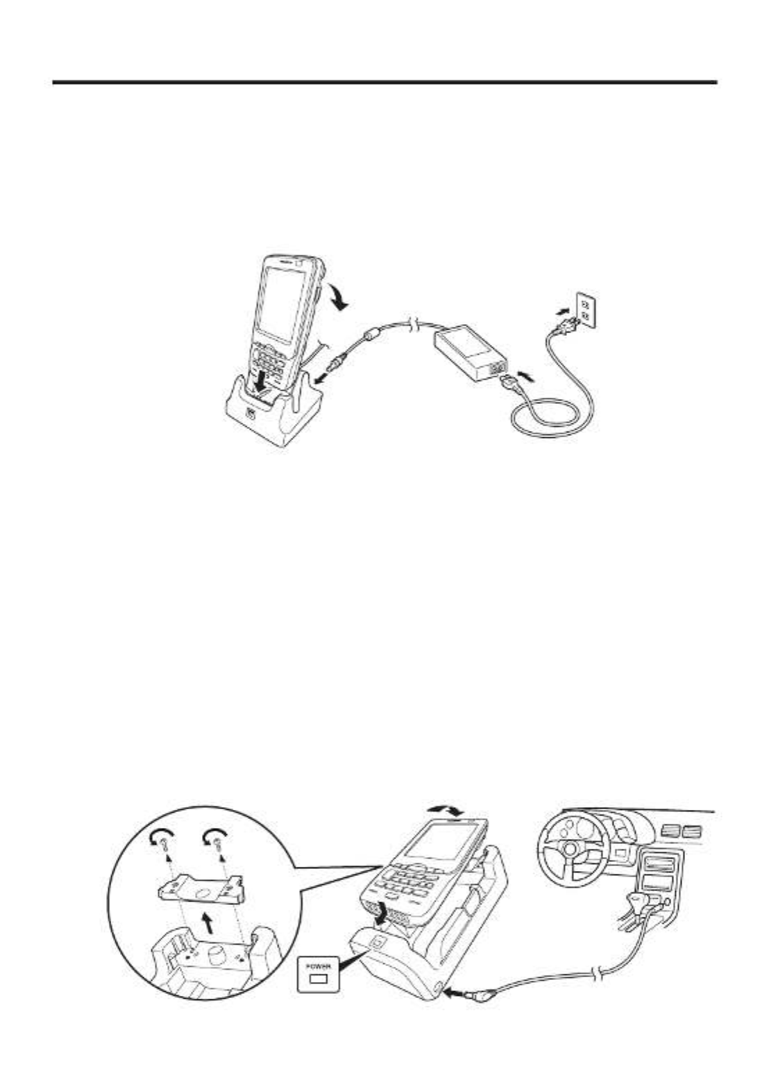
USB Cradle/Ethernet Cradle/Cradle-type Battery Charger
AD-S42120C-N5
AD-S42120B
Status of Indicator 1 on IT-800:
Orange: Charging
Red: Standby due to battery pack error or the surrounding temperature is out of the
charging temperature range
(charging begins when the temperature is within the charging temperature range)
Green: Charging complete
Car Mounted-type Battery Charger
Before the use of the Car Mounted-type Battery Charger for WWAN models, remove a
small plate (see the fi gure below) on the charger.
For other models, you do not need to remove the plate. Proceed the step below.
Plug in the Car Power Cable accompanied in the box to the Car Mounted-type Battery
Charger as illustrated below and the other end to the cigarette lighter socket in vehicle.
The power LED on the front of the Car Mounted-type Battery Charger will light green
if the Handheld Terminal has been properly mounted.
Status of Indicator 1 on IT-800:
Refer to “USB Cradle/Ethernet Cradle/Cradle-type Battery Charger” above.

E-23
Dual Battery Charger
Taking care that the battery pack is oriented correctly, insert it into the Dual Battery
Charger.
This causes the Charge Indicator LED to light in red, indicating that charging has
started.
AD-S42120C-N5
AD-S42120B
You can connect up to three Dual Battery Chargers.
Status of Charge Indicator LED
Off: Not charging
Red: Charging
Red Flashing: Battery pack problem
Green: Charging complete
Green Flashing: Standby due to the surrounding temperature being beyond the
specifi ed temperature range (Approximately 0°- 40°C) (charging
resumes when the temperature reaches the range.)
AC Adaptor
AD-S15050B
Status of Indicator 1 on IT-800:
Refer to “USB Cradle/Ethernet Cradle/Cradle-type Battery Charger” on the previous
page.

E-24
Handling the Hand Belt
The hand belt is attached to the terminal. Remove it if it is not necessary.
To remove the hand belt
1. As shown in the fi gure, pull out the metal part of the hook while pressing down the
protrude part that has a small dimple on it.
2. Loose the hook-loop fastener and then pull out the belt through the hand belt hook as
shown in the fi gure.
To attach the hand belt
1. Thread one end of the hand belt through the hand belt hook. Then fold it back and set
the belt in proper length by adjusting the hook-loop fastener.
2. As shown in the fi gure, align the metal part of the hand belt hook in line with the
installation position on the terminal and then snap it into the ditch. Make sure that the
metal part is fi rmly seated.

E-25
Connecting the Stylus String
The string can be connected to stylus and hand belt to prevent loss of stylus or
misplacing. Follow the instruction below to connect it to stylus and hand belt.
1. Thread one end of the string through the slit on stylus as shown in the illustration.
2. Thread the other end of the string through the loop as shown in the illustration, and
then pull the other end to tighten.
3. Unhook one end of the hand belt from IT-800 if it is attached, and then thread the
hand belt through the loop of the string as shown in the illustration.
For unhooking the hand belt from the terminal, refer to “To remove the hand belt” on
page 24.
4. Hook the end of the hand belt to the terminal. Refer to “To attach the hand belt” on
page 24.

E-26
Attaching the Neck Strap
The neck strap can be used to prevent the Handheld Terminal from fall when carrying
it around. Since there are two strap holes where the neck strap can be attached, use
the hole that affords the ease of use. Attach the neck strap according to the procedure
described below.
To attach the neck strap
1. Pass the thin cord of the neck strap through the strap hole on the back of the
Handheld Terminal.
2. Pass the other end of the strap (the part you put around your neck) through the loop
formed by the thin cord.
Important!
Do not swing the Handheld Terminal around holding the neck strap.

E-27
Confi guring Handheld Terminal Settings
Calibrating Touch Screen Alignment
Whenever the response of the touch screen is poor, or operation being executed does
not match with the location you are tapping on the touch screen, please recalibrate the
alignment of the touch screen using the following method.
Press the “Fn” key and then press the “4” key after confi rming that “F” is displayed
in the lower right corner of the screen. The following screen is displayed.
∗ You can also display this screen by navigating as follows:
Start Settings System Screen Align Screen
Press the stylus against the center of the target mark (+ mark) as indicated on the
screen.
After the calibration is complete, the terminal resumes a screen automatically
according to the method carried out to initiate the calibration.
If you start the calibration by pressing "Fn" and "4" keys, the terminal resumes Start
screen, or General tab screen of Settings mode which is the screen one before align
screen of Settings mode if you initiate by navigating to the icons.
•
•

E-28
Adjusting Display Brightness
You can use the following procedures to adjust display brightness to make it easier to
read under different lighting conditions.
Press the “Fn” key and then press the “5” key or “6” key after confi rming that “F”
is displayed in the lower right corner of the screen. Pressing the “5” key adjusts
brightness for a darker display, while pressing the “6” key adjusts brightness for a
lighter display.
∗ In order to continue to make adjustments, press the “5” key or “6” key again after
fi rst pressing the “Fn” key.
∗ Brightness settings can also be made by navigating to the menus and tab in order of
Start ➝ Settings ➝ System ➝ Backlight.
Display Auto Dimmer
The display auto dimmer automatically lowers display brightness if you do not
perform any operation for a specifi c period of time. This helps the battery power to be
conserved.
You can use the following procedure to specify a period of time that should be allowed
to elapse until when the auto dimming is initiated.
Navigate to the menus and tab in order of Start
➝ Settings ➝ System ➝ Backlight.
•
•

E-29
Using the Laser Scanner (Laser Models)
1. After turning on the power, position the laser scanner close to a bar code and then
press the trigger key.
2. The laser emits light and scans the bar code. If scanning is completed normally,
Indicator 2 displays a green light.
Important!
If you are unable to scan a bar code, try changing the angle at which the scanner
is held or distance from the scanner to the bar code, and then try scanning
again.
This Handheld Terminal is capable of scanning bar codes at a distance of
about 40-400 mm (19/16"-153/4"). Furthermore, the distance at which
scanning is possible may vary according to the bar code symbology.
•
•
E-30
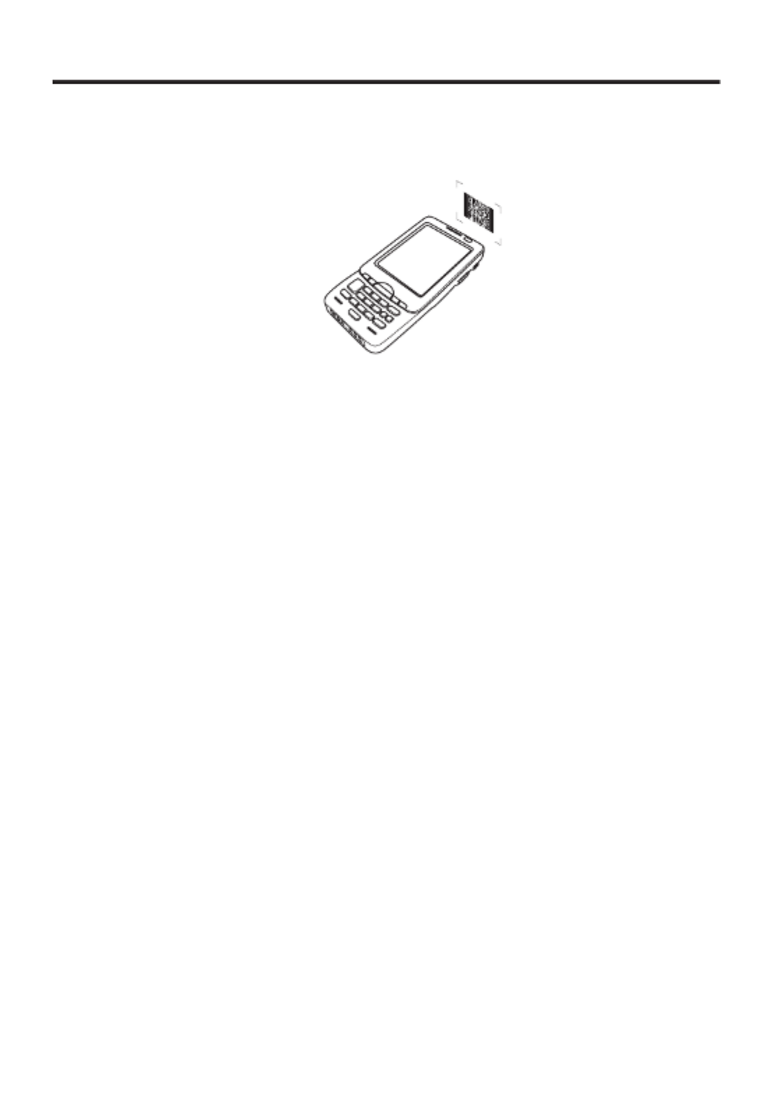
Using the C-MOS Imager (Imager Models)
1. Turn on the Handheld Terminal, position its C-MOS Imager reader port near the bar
code or 2D code, and then press the trigger key.
2. The Handheld Terminal reads the code by emitting laser and red lights.
Indicator 2 (read operation indicator lamp) lights in green when the reading is
successful.
Bar code and stacked 2D code Reading Guide
When you press the trigger key, LEDs in the Handheld Terminal emit laser and red
lights. Align the laser frame with the center of the bar code or 2D code you are trying
to read. Take particular care aligning the light when there are other bar codes nearby.
When reading a bar code in large size, adjust the position of the Handheld Terminal
so that the entire code is enclosed within the laser frame. For small size, move the
Handheld Terminal closer to it.
Important!
If you have problem not properly reading a code, change the angle and/or the
distance between the code and the Handheld Terminal and try reading it again.
A bar code can be read from a distance of 45mm to 410mm (1
3/4" to 161/8"),
and a stacked 2D code can be read from a distance of 65mm to 260mm (2
9/16"
to 101/4") and matrix 2D code can be read from a distance of 55mm to 195mm
(23/16" to 711/16"). The actual reading distance depends on the symbology and the
resolution.
Note that a special reader application is required to read bar codes and 2D
codes.
Fingerprints, dust, dirt, or stain on the C-MOS Imager reader port can cause
abnormal reading. Should the reader port become dirty, wipe it clean with a soft
and dry cloth.
•
•
•
•
E-31
Adjusting the Laser Light Emission Width
The emission width of the laser light emitted by the Handheld Terminal (model
dependant) can be adjusted. Adjust the emission width when it is improper.
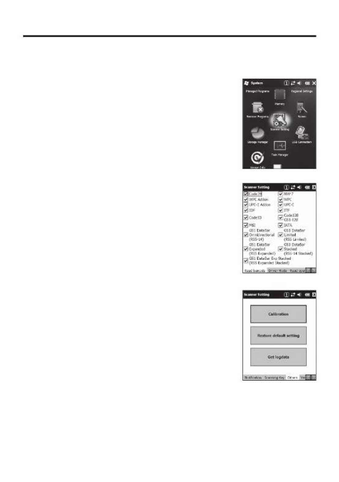
1. Navigate to the menus in the following sequence:
Start Settings System
The Control Panel appears as shown in the screen.
2. Tap the [Scanner Setting] icon. The Setting screen
appears as shown in the screen.
3. Tap the [Others] tab in the Scanner Setting screen.
E-32
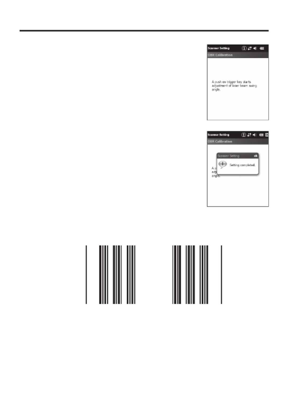
4. Tap the [Calibration] button. The display appears as
shown at right.
5. Press the trigger key to emit laser light, and align the
light with the barcode for adjusting emission width.
Align the laser light with the narrow bars on both sides.
The message appears as shown at right when adjustment
is completed.
Repeat the setting if “Setting failed” message appears.
Emission Width Adjustment Bar code
•
•
•

E-33
Handling the NFC
The NFC is a technology of contactless IC card for short range communication that
enables writing data to card and reading data from the card by applying the card close
to the screen on IT-800.
The integrated NFC can read a contactless IC card used typically for employment
identifi cation, etc.
1. Apply a card so that it is positioned in parallel with the screen.
Important!
If reading a card is diffi cult, slightly change the position by moving it either close
to the screen or far away, or to the right or to the left.
Do not apply card with force to the screen so that hit the screen by the card can
be avoided.
Do not apply card while it is overridden by other card. The NFC may not read it
correctly.
A metal object near by the screen may cause the NFC not to read card correctly.
Take the card out of a wallet if the wallet is with metal object before applying it
to the screen.
Apply card in parallel with the screen to touch the screen surface with the card.
The NFC employs a low power radio wave which does not require regulatory
station license.
Frequency band used by the NFC is 13.56 MHz. Secure a suffi cient space
between IT-800 and other reader/writer located in the vicinity. Make sure also
that a radio station employs the same frequency band does not locate near by
prior to using IT-800.
•
•
•
•
•
•
•

E-34
Performing Communications
IR Communication
IR communication can be used to transfer data between two Handheld Terminals.
When performing IR communication, orient the IR ports of both Handheld Terminals
so they are pointing directly at each other.
The ports can be in direct contact with each other, or they can be separated by up to
30cm (1113⁄16") (up to 20cm (7 7⁄8") for communication between units).
Important!
A high sensitivity communication element is used during IR communication.
In order to ensure successful communication, avoid using cellular phones
or other devices that emit radio wave in the area where you are performing
IR communication. If you need to use such a device, move away from the
communicating Handheld Terminals. In case of a cellular phone, keep it at least
30cm (1113⁄16") away.
•
•

E-35
Bluetooth® Communication
Bluetooth® interface can also be used to transfer data between two Handheld Terminals.
With Bluetooth® the two Handheld Terminals should be located within about three meters
(9'103⁄8") from each other, as long as there is nothing blocking the path between them.
Important!
Observe the following precautions to help ensure that Bluetooth communication is
successful.
Make sure two Handheld Terminals face each other within three meters (9
'103⁄8").
Surroundings (obstacles) between the Handheld Terminals may cause a shorter
distance.
Make sure there is at least two meters (6'7") between the Handheld Terminal and
other equipment (electrical appliances, audio-visual equipment, OA equipment,
and digital cordless telephones, facsimile machines, etc.). Take special care with
microwave ovens. Allow at least three meters (9'103⁄8) between the Handheld
Terminals in wireless operation and a microwave oven. When operating the
terminal in Bluetooth nearby these devices and electrical appliances with their
powers being turned on, communication may be interrupted or TV and radio
receptions may be interfered (images on the screen produced by certain channels
of UHF and broadcast satellite may become blurry).
Normal communication may not be possible in an area near a broadcast trans-
mitter or wireless transmitter. If this happens, move the Handheld Terminal to a
different location. Normal communication may not be possible in areas exposed
to strong radio waves.
Interference by WLAN
Because Bluetooth® and WLAN use the same frequency band (2.4GHz), radio
interference can occur if there is a WLAN device nearby. This can result in lower
communication speed, or even make it impossible to establish a connection. If
this happens, try the following countermeasures.
Move at least 10 meters (32'103⁄4") away from the WLAN device.
If you cannot keep the distance at least 10 meters (32
'103⁄4") or more between the
Handheld Terminal and a WLAN device, turn off the power of either the Handheld
Terminal or the WLAN device.
Although the Handheld Terminal enables WLAN and Bluetooth
® communication
to be used simultaneously as a result of being equipped with Bluetooth
® Ver.2.0,
communication may not be possible depending on the surrounding radio wave
environment.
•
•
•
•
•
•
•

E-36
GSM/W-CDMA Communication
To use the GSM/W-CDMA functions, you must receive service from a wireless service
provider. Available GSM/W-CDMA functions may be dependent on the service provider
to which you connect. Please consult your service provider for details about network
service.
If you use GSM/W-CDMA and WLAN at the same time, the communication speed of
WLAN may be reduced, or the reception of WLAN signals may be disconnected, due to
the operational state of GSM/W-CDMA.
GPS
When you use the Handheld Terminal for the fi rst time or after an extended period of no
use, it may take a long time before the Handheld Terminal determines its positioning. In
such a case, operate the GPS mode where there are no obstacles in the surroundings and
wait for at least 15 minutes or longer.
The GPS module integrated in the Handheld Terminal uses signals emitted by the
satellites operated by the government of the United Sates. The accuracy of positioning
information you obtain on the Handheld Terminal may be affected by the condition of
these satellites.
The GPS module may not be able to receive the signals in locations such as inside
a building or in a tunnel. If you are installing the device in your car, determine the
installation location after making sure that it can receive the signals.

E-37
Handling microSD Cards
The Handheld Terminal supports microSD card.
The employment of microSD card slot is dependent on model. See page 18 for the
models with microSD card slot integrated.
Since the microSD card slot is located inside the battery pack compartment, fi rst
remove the battery pack when installing or removing a microSD card.
Refer to pages 19 to 21 for information on “Loading and Removing the Battery Pack”.
Install (or remove) a microSD card according to the procedure described below.
Installing
1. Make sure that the power on the terminal has been switched off. If the power is still
on, press the power key to switch off.
2. Remove the battery pack.
3. Insert microSD card with the description side face up.
Make sure that the card is pushed into the slot until the small plastic spring plate is
rebounded so that the plate can fi rmly lock the card in the slot.
Avoid inserting the card diagonally.
4. Load the battery pack.
•
•

E-38
Removing
1. Make sure that the power on the terminal has been switched off. If the power is still
on, press the power key to switch off.
2. Remove the battery pack.
3. As shown in the fi gure, pull out the card while pressing down the small plastic spring
plate.
4. Load the battery pack.
Important!
A microSD card must be inserted with the top and bottom properly aligned
and in the proper direction. Attempt in inserting it with an excessive force in
incorrect orientation can risk damage to the connectors and slot.
The battery pack will not be able to be properly installed if the microSD card is
not properly installed. Reinstall the microSD card properly if this happens.
Since data recorded in the Handheld Terminal may be lost if the battery pack
is removed for more than 10 minutes, complete the installation (or removing) of
microSD card within 10 minutes.
Never turn off the power or remove a microSD card from the slot while the card
is being accessed. Doing so can damage the microSD card or data in the card.
Do not drop the card or lose it.
•
•
•
•
•

E-39
Handling SIM Cards
The Handheld Terminal supports SIM card.
The employment of SIM card slot is dependent on model. See page 18 for the models
with SIM card slot integrated.
Since the SIM card slot is located inside the battery pack compartment, fi rst remove the
battery pack when installing or removing a SIM card.
Refer to pages 19 to 21 for information on “Loading and Removing the Battery Pack”.
Install (or remove) a SIM card according to the procedure described below.
Installing
1. Make sure that the power on the terminal has been switched off. If the power is still
on, press the power key to switch off the power.
2. Remove the battery pack.
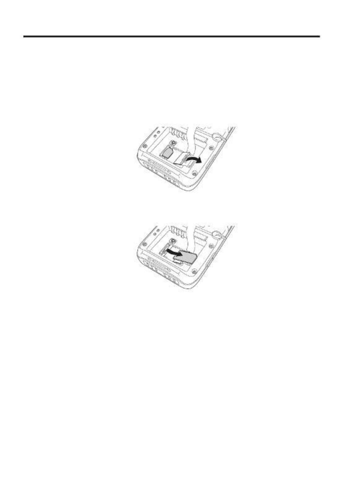
3. Put your fi nger’s nail into the slit of the plastic holder, and then lift it up. See the
fi gure below.
4. Load SIM card by sliding into the SIM card slot.
5. Make sure that the card has been inserted fi rmly and then put back the plastic holder
to its home position until you hear a click sound.
6. Load the battery pack.
E-40
Removing
1. Make sure that the power on the terminal has been switched off. If the power is still
on, press the power key to switch off.
2. Remove the battery pack.
3. Put your fi nger’s nail into the slit of the plastic holder, and then lift it up. See the
fi gure below.
4. Pull the SIM card out of the slot by sliding it to the direction shown by the arrow. See
the fi gure below.
5. Put back the plastic holder to its home position until you hear a click sound.
6. Load the battery pack.
Important!
A SIM card must be inserted with the top and bottom properly aligned and in
the proper direction. Attempt in inserting it with an excessive force in incorrect
orientation can risk damage to the connectors and slot.
The battery pack will not be able to be properly installed if the SIM card is not
properly installed. Reinstall the SIM card properly if this happens.
Since data recorded in the Handheld Terminal may be lost if the battery pack
is removed for more than 10 minutes, complete the installation (or removing) of
SIM card within 10 minutes.
•
•
•

E-41
Handling SD Memory Cards
SD memory card can be installed in the SD memory card slot on the Handheld
Terminal.
The employment of SD memory card slot is dependent on model. See page 18 for the
models with SD memory card slot integrated.
Install (or remove) an SD memory card according to the procedure described below.
Installing
1. Open the cover of the SD memory card slot ( ) and insert an SD memory card all
the way in until the top of the SD memory card aligns with the entrance of the slot of
the Handheld Terminal ( ).
1
2
2. Close the cover of the SD memory card slot.
Important!
An SD memory card must be inserted with the top and bottom properly aligned
and in the proper direction. Attempt in inserting it with an excessive force in
incorrect orientation can risk damage to the connectors and slot.
Never turn off the power or remove an SD memory card from the slot while the
card is being accessed. Doing so can damage the SD memory card or data in the
card.
Do not drop the card or lose it.
Removing
1. Open the cover of the SD memory card slot and press on the SD memory card ( ).
The SD memory card is pushed out ( ).
12
2. Pull out the SD memory card and close the cover of the SD memory card slot.
•
•
•

E-42
Resetting the Handheld Terminal
Resetting the terminal is the same as resetting a PC. Performing a reset causes all
unsaved RAM data to be lost that are in mid-course of inputting and editing, but data
and settings that are already stored in the FlashROM should be unaffected.
Perform a reset to restore normal operation whenever the Handheld Terminal operates
abnormally due to misoperation or some other reason.
Use a stylus to press the reset switch on the back of the IT-800.
This starts the reset operation.
Do not use a toothpick or pencil or other sharp
object whose tip may break off the reset switch.
Performing a Full Reset (Initialization)
Performing a full reset deletes all data and resets various settings to their defaults.
*Data stored in the Flashdisk folder remain unaffected.
Perform a full reset whenever any one of the following conditions exists.
When you want to delete installed programs and settings, and resume the terminal to
the initial condition.
When you are no longer able to use the Handheld Terminal because you forgot your
password.
When the Handheld Terminal does not operate normally due to a memory problem.
Important!
Performing a full reset resets all data to their defaults except stored in the
Flashdisk folder. If possible, backup data of the terminal to a PC or to the
Flashdisk folder. The reset procedure and display message appeared on
performing the reset is according to the model you operate.
*
•
•
•

E-43
1. Hold down Fn key and CLR key while pushing down the reset switch for about 3
seconds with the tip of a stylus until the message shown below appears on the display.
To cancel the full reset operation, press L Trigger key on the scan engine integrated
models or Up key on the non-scan engine integrated models.
Message appeared on the scan engine integrated models.
R Trigger
key
Message appeared on the non-scan engine integrated models.
2. Press R Trigger key on the scan engine integrated models or R Enter key on the non-
scan engine integrated models. This causes the message shown below to appear.
To cancel the full reset operation, press L Trigger key on the scan engine integrated
models or Up key on the non-scan engine integrated models.
Message appeared on the scan engine integrated models.
R Trigger
key
Message appeared on the non-scan engine integrated models.
3. Press R Trigger key or R Enter key again to perform the full reset.
The full reset starts and all data in the memory are erased, and the start-up screen
appears.
Data stored in the Flashdisk folder remain unaffected.
•
•
•
Termékspecifikációk
| Márka: | Casio |
| Kategória: | Doboz |
| Modell: | IT-800 |
Szüksége van segítségre?
Ha segítségre van szüksége Casio IT-800, tegyen fel kérdést alább, és más felhasználók válaszolnak Önnek
Útmutatók Doboz Casio

3 Szeptember 2024
3 Szeptember 2024
3 Szeptember 2024
3 Szeptember 2024
3 Szeptember 2024
3 Szeptember 2024
3 Szeptember 2024
3 Szeptember 2024
3 Szeptember 2024
3 Szeptember 2024
Útmutatók Doboz
- Doboz Samsung
- Doboz Sharp
- Doboz Toshiba
- Doboz HP
- Doboz Miele
- Doboz Zebra
- Doboz Crestron
- Doboz Qian
- Doboz ATen
- Doboz Olympia
- Doboz Posiflex
- Doboz Newland
- Doboz CUSTOM
- Doboz Elo
- Doboz Equip
- Doboz Royal Sovereign
- Doboz SAM4s
- Doboz Olivetti
- Doboz Barska
- Doboz Intermec
- Doboz J2 Retail Systems
- Doboz Advantech
- Doboz IZettle
- Doboz VeriFone
- Doboz Vectron
- Doboz Flytech
- Doboz Cambro
- Doboz AOpen
- Doboz EC Line
- Doboz Approx
- Doboz Colormetrics
- Doboz MyPOS
Legújabb útmutatók Doboz

4 Január 2025
1 Január 2025
29 December 2024
29 December 2024
29 December 2024
29 December 2024
28 December 2024
28 December 2024
28 December 2024
28 December 2024