Használati útmutató Asrock X99 Taichi
Olvassa el alább 📖 a magyar nyelvű használati útmutatót Asrock X99 Taichi (98 oldal) a alaplap kategóriában. Ezt az útmutatót 3 ember találta hasznosnak és 2 felhasználó értékelte átlagosan 4.5 csillagra
Oldal 1/98


Version 1.0
Published June 2016
Copyright©2016 ASRock INC. All rights reserved.
Copyright Notice:
No part of this documentation may be reproduced, transcribed, transmitted, or
translated in any language, in any form or by any means, except duplication of
documentation by the purchaser for backup purpose, without written consent of
ASRock Inc.
Products and corporate names appearing in this documentation may or may not
be registered trademarks or copyrights of their respective companies, and are used
only for identication or explanation and to the owners’ benet, without intent to
infringe.
Disclaimer:
Specications and information contained in this documentation are furnished for
informational use only and subject to change without notice, and should not be
constructed as a commitment by ASRock. ASRock assumes no responsibility for
any errors or omissions that may appear in this documentation.
With respect to the contents of this documentation, ASRock does not provide
warranty of any kind, either expressed or implied, including but not limited to
the implied warranties or conditions of merchantability or tness for a particular
purpose.
In no event shall ASRock, its directors, ocers, employees, or agents be liable for
any indirect, special, incidental, or consequential damages (including damages for
loss of prots, loss of business, loss of data, interruption of business and the like),
even if ASRock has been advised of the possibility of such damages arising from any
defect or error in the documentation or product.
is device complies with Part 15 of the FCC Rules. Operation is subject to the following
two conditions:
(1) this device may not cause harmful interference, and
(2) this device must accept any interference received, including interference that
may cause undesired operation.
CALIFORNIA, USA ONLY
e Lithium battery adopted on this motherboard contains Perchlorate, a toxic substance
controlled in Perchlorate Best Management Practices (BMP) regulations passed by the
California Legislature. When you discard the Lithium battery in California, USA, please
follow the related regulations in advance.
“Perchlorate Material-special handling may apply, see www.dtsc.ca.gov/hazardouswaste/
perchlorate”
ASRock Website: http://www.asrock.com
AUSTRALIA ONLY
Our goods come with guarantees that cannot be excluded under the Australian Consumer
Law. You are entitled to a replacement or refund for a major failure and compensation for
any other reasonably foreseeable loss or damage caused by our goods. You are also entitled
to have the goods repaired or replaced if the goods fail to be of acceptable quality and the
failure does not amount to a major failure. If you require assistance please call ASRock Tel
: +886-2-28965588 ext.123 (Standard International call charges apply)
Manufactured under license under U.S. Patent Nos: 5,956,674; 5,974,380; 6,487,535;
7,003,467 & other U.S. and worldwide patents issued & pending. DTS, the Symbol, &
DTS and the Symbol together is a registered trademark & DTS Connect, DTS Interactive,
DTS Neo:PC are trademarks of DTS, Inc. Product includes soware.
© DTS, Inc., All Rights Reserved.

Contents
Chapter 1 Introduction 1
1.1 Package Contents 1
1.2 Specications 2
1.3 Motherboard Layout 7
1.4 I/O Panel 9
1.5 WiFi-802.11ac Module and ASRock WiFi 2.4/5 GHz Antenna 11
Chapter 2 Installation 13
2.1 Installing the CPU 14
2.2 Installing the CPU Fan and Heatsink 17
2.3 Installation of Memory Modules (DIMM) 18
2.4 Expansion Slots (PCI Express Slots) 20
2.5 Jumpers Setup 22
2.6 Onboard Headers and Connectors 23
2.7 Smart Switches 28
2.8 Dr. Debug 29
2.9 SLITM , 3-Way SLITMand Quad SLITM Operation Guide 31
2.9.1 Installing Two SLITM-Ready Graphics Cards 31
2.9.2 Installing Three SLITM-Ready Graphics Cards 33
2.9.3 Driver Installation and Setup 35
2.10 CrossFireXTM, 3-Way CrossFireXTM and Quad CrossFireXTM
Operation Guide 36
2.10.1 Installing Two CrossFireXTM-Ready Graphics Cards 36

2.10.2 Installing Three CrossFireXTM-Ready Graphics Cards 38
2.10.3 Driver Installation and Setup 39
2.11 M.2_SSD (NGFF) Module Installation Guide 40
Chapter 3 Software and Utilities Operation 43
3.1 Installing Drivers 43
3.2 A-Tuning 44
3.3 ASRock Live Update & APP Shop 48
3.3.1 UI Overview 48
3.3.2 Apps 49
3.3.3 BIOS & Drivers 52
3.3.4 Setting 53
Chapter 4 UEFI SETUP UTILITY 54
4.1 Introduction 54
4.2 EZ Mode 55
4.3 Advanced Mode 56
4.3.1 UEFI Menu Bar 56
4.3.2 Navigation Keys 57
4.4 Main Screen 58
4.5 OC Tweaker Screen 59
4.6 Advanced Screen 70
4.6.1 CPU Conguration 71
4.6.2 Chipset Conguration 73
4.6.3 Storage Conguration 76
4.6.4 Super IO Conguration 77

4.6.5 ACPI Conguration 78
4.6.6 USB Conguration 79
4.6.7 Trusted Computing 81
4.7 Tools 82
4.8 Hardware Health Event Monitoring Screen 85
4.9 Security Screen 87
4.10 Boot Screen 88
4.11 Exit Screen 91

English
2
1.2 Specications
Platform • ATX Form Factor
• 8 Layer PCB
• 4 x 2oz Copper
CPU • Supports Intel® CoreTM i7 and Xeon® 18-Core Processors
Family for the LGA 2011-3 Socket
• Digi Power design
• 12 Power Phase design
• Supports Intel® Turbo Boost Max Technology 3.0
* Intel® CoreTM i7-59xx/58xx processors only support Intel®
Turbo Boost Max Technology 2.0.
• Supports Untied Overclocking Technology
Chipset • Intel® X99
Memory • Quad Channel DDR4 Memory Technology
• 8 x DDR4 DIMM Slots
• Supports DDR4 3300+(OC)*/2933(OC)/2800(OC)/2400
(OC)/2133 non-ECC, un-buered memory
* Please refer to Memory Support List on ASRock's website for
more information. (http://ww w.asrock.com/)
• Supports non-ECC RDIMM (Registered DIMM)
• Supports DDR4 ECC, un-buered memory/RDIMM with
Intel® Xeon® processors E5 series in the LGA 2011-3 Socket
• Max. capacity of system memory: 128GB
• Supports Intel® Extreme Memory Prole (X MP) 2.0
• 15μ Gold Contact in DIMM Slots
Expansion
Slot
• 3 x PCI Express 3.0 x16 Slots (PCIE2 @ x16 mode; PCIE4 @
x16 mode; PCIE5 @ x0 mode) (PCIE2 @ x16 mode; PCIE4 @
x8 mode; PCIE5 @ x8 mode)
* If you install CPU with 28 lanes, PCIE2/PCIE4/PCIE5 will
run at x16/x0/x8 or x8/x8/x8.
* Supports NVMe SSD as boot disks
• 2 x PCI Express 2.0 p8-x1 Slots

English
X99 Taichi
3
• Supports AMD Quad CrossFireXTM, 3-Way CrossFireXTM
and CrossFireXTM
• Supports NVIDIA® Quad SLITM, 3-Way SLITM and SLITM
• 1 x Vertical M.2 Socket (Key E), supports type 2230 WiFi/BT
module
* e M.2 socket does not support SATA M.2 SSDs.
• 15μ Gold Contact in VGA PCIe Slot (PCIE2 and PCIE4)
Audio • 7.1 CH HD Audio with Content Protection (Realtek
ALC1150 Audio Codec)
• Premium Blu-ray Audio support
• Supports Surge Protection (ASRock Full Spike Protection)
• Supports Purity SoundTM 3
- Nichicon Fine Gold Series Audio Caps
- 115dB SNR DAC with Dierential Amplier
- TI® NE5532 Premium Headset Amplier (Supports up to
600 Ohm headsets)
- Pure Power-In
- Direct Drive Technology
- PCB Isolate Shielding
• Supports DTS Connect
LAN • Gigabit LAN 10/100/1000 Mb/s
• 1 x Giga PHY Intel® I218V, 1 x GigaLAN Intel® I211AT
• Supports Wake-On-LAN
• Supports Lightning/ESD Protection (ASRock Full Spike
Protection)
• Supports Dual LAN with Teaming
* Windows® 10 is not supported.
• Supports Energy Ecient Ethernet 802.3az
• Supports PXE
Wireless
LAN
• Supports IEEE 802.11a/b/g/n/ac
• Supports Dual-Band (2.4/5 GHz)
• Supports high speed wireless connections up to 433Mbps
• Supports Bluetooth 4.0 / 3.0 + High speed class II
Rear Panel
I/O
• 1 x PS/2 Mouse/Keyboard Port
• 1 x Optical SPDIF Out Port

English
4
• 3 x USB 2.0 Ports (Supports ESD Protection (ASRock Full
Spike Protection))
• 1 x USB 3.1 Type-A Port (10 Gb/s) (ASMedia ASM1142)
(Supports ESD Protection (ASRock Full Spike Protection))
• 1 x USB 3.1 Type-C Port (10 Gb/s) (ASMedia ASM1142)
(Supports ESD Protection (ASRock Full Spike Protection))
• 3 x USB 3.0 Ports (Intel® X99) (Supports ESD Protection
(ASRock Full Spike Protection))
• 2 x RJ-45 LAN Ports with LED (ACT/LINK LED and SPEED
LED)
• 1 x Clear CMOS Switch
• HD Audio Jacks: Rear Speaker / Central / Bass / Line in /
Front Speaker / Microphone
Storage • 10 x SATA3 6.0 Gb/s Connectors, support RAID (RAID 0,
RAID 1, RAID 5, RAID 10, Intel Rapid Storage Technology
13), NCQ, AHCI and Hot Plug
* SSATA3_3 connector is shared with the M2_1; SSATA3_2
connector is shared with the M2_2
* RAID is supported on SATA3_0 ~ SATA3_5 ports only.
• 1 x SATA Express 10 Gb/s Connector (shared with SATA3_4
and SATA3_5)
* Support to be announced
• 1 x Ultra M.2 Socket (M2_2), support type
2230/2242/2260/2280/22110 M.2 SATA3 6.0 Gb/s module
and M.2 PCI Express module up to Gen3 p10-x4 (32 Gb/s)**
• 1 x Ultra M.2 Socket (M2_1), support type
2230/2242/2260/2280 M.2 SATA3 6.0 Gb/s module and M.2
PCI Express module up to Gen3 p10-x4 (32 Gb/s)**
* If you install CPU with 28 lanes, the M2_1 only supports
SATA type M.2 module.
** Supports NVMe SSD as boot disks
** Supports ASRock U.2 Kit
Connector • 1 x COM Port Header
• 1 x TPM Header
• 1 x Power LED and Speaker Header
• 1 x CPU Fan Connector (4-pin)
* e CPU Fan Connector supports the CPU fan of maximum
1A (12W) fan power.

English
X99 Taichi
5
• 1 x CPU Optional/Water Pump Fan Connector (4-pin)
* e CPU Optional/Water Pump Fan supports the water cooler
fan of maximum 1.5A (18W) fan power.
• 3 x Chassis Fan Connectors (4-pin)
* CHA_FAN1 and CHA_FAN2 can auto detect if 3-pin or 4-pin
fan is in use.
• 1 x 24 pin ATX Power Connector
• 1 x 8 pin 12V Power Connector (Hi-Density Power Connec-
tor)
• 1 x Front Panel Audio Connector
• 2 x USB 2.0 Headers (Support 4 USB 2.0 ports) (Supports
ESD Protection (ASRock Full Spike Protection))
• 1 x USB 3.0 Header (Supports 2 USB 3.0 ports) (Supports
ESD Protection (ASRock Full Spike Protection))
• 1 x Dr. Debug with LED
• 1 x BIOS Selection Switch
BIOS
Feature
• 2 x AMI UEFI Legal BIOS with multilingual GUI support
(1 x Main BIOS and 1 x Backup BIOS)
• Supports Secure Backup UEFI Technology
• ACPI 5.0 Compliant wake up events
• SMBIOS 2.7 Support
• CPU, DRAM, PCH 1.05V, PCH 1.5V, VPPM Voltage Multi-
adjustment
Hardware
Monitor
• CPU/Chassis/ CPU Optional/Water Pump Fan temperature
sensing
• CPU/Chassis/ CPU Optional/Water Pump Tachometer
• CPU/Chassis/ CPU Optional/Water Pump Quiet Fan (Auto
adjust chassis fan speed by CPU temperature)
• CPU/Chassis/ CPU Optional/Water Pump Fan multi-speed
control
• Voltage monitoring: +12V, +5V, +3.3V, CPU Input Voltage,
CPU Internal Voltages
OS • Microso® Windows® 10 64-bit / 8.1 64-bit / 8 64-bit / 7 32-
bit / 7 64-bit
English
6
Please realize that there is a certain risk involved with overclocking, including adjusting
the setting in the BIOS, applying Untied Overclocking Technology, or using third-party
overclocking tools. Overclocking may aect your system’s stability, or even cause damage to
the components and devices of your system. It should be done at your own risk and expense.
We are not responsible for possible damage caused by overclocking.
Due to limitation, the actual memory size may be less than 4GB for the reservation for sys-
tem usage under Windows® 32-bit operating systems. Windows® 64-bit operating systems
do not have such limitations. You can use ASRock XFast RAM to utilize the memory that
Windows® cannot use.
* For detailed product information, please visit our website:
http://www.asrock.com
Certica-
tions
• FCC, CE, WHQL
• ErP/EuP Ready (ErP/EuP ready power supply is required)

English
X99 Taichi
7
Intel
X99
ATX 112V
ATXPWR1
1
USB 3_1_2
LAN
LAN
PCIE2
To p:
Cent ral/Bass
Cen te r:
REA R SPK
To p:
LIN E IN
Cen te r:
FRO NT
Bot to m:
Opt ic al
SPD IF
Bot to m:
MIC I N
PCIE4
HD LED ES ET R
PLE D PWRB T N
PANE L1
1
USB 5_6
11
USB 3_4
CO M 1
1
1
HD_AUDIO1
X 9 9
Ta i c h i
PCIE5
SATA3 _0_ 3
SATA3 _1_ 4
SATA3 _2_ 5
PCIE3
CP U_FAN 1
CPU _OP T / W_P UM P
Ro HS
8
10
11
9
14
15
16
17
18
19202227
CLRC
BT N1
To p:
RJ -4 5
US 3.B 0
T: 3USB
B: USB4
SSATA 3_0 _1
SSA A3 _3 SSA A3 _2T T
3 4 7
DDR4_ A2 (64 bit, 288 - pi n m o dule)
DDR4_ A1 (64 bit, 288 - pi n m o dule)
DDR4_ B2 (64 b i t, 28 8-pin module )
DDR4_ B1 (64 b i t, 28 8-pin module )
21
25 2324
Pu r ity
S 3ou nd
T M
BIOS _ B _ LE D
BI OS_ B1
BIO S BIO S
BI OS_ A1
BIOS _ L E D_ A _ B
1
T PMS 1
CMOS
Battery
CLR M O S1
1
M2_WIFI
CH A_F AN2
CH A_F AN3
CH A_F AN1
26 21
12
13
28
M2
CT 5 NUT 2 _0NUT 2 _1N UT 2_ 2NUT 2 _3
DDR4_ D1 (64 b i t, 28 8-pin module )
DDR4_ D2 (64 b i t, 28 8-pin module )
DDR4_ C1 (64 b i t, 28 8-pin module )
DDR4_ C2 (64 b i t, 28 8-pin module )
65
20 11- So ck e3 t
Dr.
Debug
BIO S_SEL 1
A B
PCIE1
USB 2.0
T: USB1
B: USB 2
PS2
Key boa r d
/Mou se
To p:
RJ -4 5
US 2.B 0
T: USB7
US 3.B 0
B: U SB5
SATAE _1
Ul tr M.a 2
PC Ie Ge n3 x4
1
SPK_ PLE D1
M2
NUT 1 _0NUT 1 _1N UT 1_ 2NUT 1 _3
US 3.B 1
T: USB 31_T A_ 1
B: USB 31_ TC _1
1.3 Motherboard Layout

English
8
No. Description
1 2 x 288-pin DDR4 DIMM Slots (DDR4_A1, DDR4_B1)
2 2 x 288-pin DDR4 DIMM Slots (DDR4_A2, DDR4_B2)
3 ATX 12V Power Connector (ATX12V1)
4 CPU Fan Connector (CPU_FAN1)
5 2 x 288-pin DDR4 DIMM Slots (DDR4_D2, DDR4_C2)
6 2 x 288-pin DDR4 DIMM Slots (DDR4_D1, DDR4_C1)
7 CPU Optional/Water Pump Fan Connector (CPU_OPT/W_PUMP)
8 ATX Power Connector (ATXPWR1)
9 Chassis Fan Connector (CHA_FAN3)
10 USB 3.0 Header (USB3_1_2)
11 SATA3 Connectors (SSATA3_3)
12 Chassis Fan Connector (CHA_FAN2)
13 SATA3 Connectors (SSATA3_2)
14 SATA3 Connectors (SSATA3_0_1)
15 SATA3 Connectors (SATA3_0_3)
16 SATA3 Connectors (SATA3_1_4)
17 SATA3 Connectors (SATA3_2_5)
18 SATA Express Connector (SATAE_1)
19 USB 2.0 Header (USB3_4)
20 USB 2.0 Header (USB5_6)
21 COM Port Header (COM1)
22 TPM Header (TPMS1)
23 System Panel Header (PANEL1)
24 Power LED and Speaker Header (SPK_PLED1)
25 BIOS Selection Switch (BIOS_SEL1)
26 Clear CMOS Jumper (CLRCMOS1)
27 Front Panel Audio Header (HD_AUDIO1)
28 Chassis Fan Connector (CHA_FAN1)

English
X99 Taichi
9
1.4 I/O Panel
No. No.Description Description
1 USB 2.0 Ports (USB12) USB 3.0 Ports (USB3_34)10
2 LAN RJ-45 Port USB 2.0 Port (USB7)11
(Intel® I211AT)* USB 3.0 Port (USB3_5)12
3 LAN RJ-45 Port USB 3.1 Type-A Port (USB31_TA_1)13
(Intel® I218V)* (ASMedia ASM1142)
4 Central / Bass (Orange) USB 3.1 Type-C Port (USB31_TC_1)14
5 Rear Speaker (Black) (ASMedia ASM1142)
6 Line In (Light Blue) Clear CMOS Switch15
7 Front Speaker (Lime)** 16 Antenna Ports
8 PS/2 Mouse/Keyboard PortMicrophone (Pink) 17
9 Optical SPDIF Out Port
CAUTION:
For operating system installation, be sure to plug your USB ash drive into the USB 2.0
Ports (USB12).
1
17 891011
12
13
14
1516
32 5
4
7
6

English
10
* ere are two LEDs on each LAN port. Please refer to the table below for the LAN port LED indications.
Activity / Link LED Speed LED
Status StatusDescription Description
O ONo Link 10Mbps connection
Blinking Data Activity Orange 100Mbps connection
On Link Green 1Gbps connection
** If you use a 2-channel speaker, please connect the speaker’s plug into “Front Speaker Jack”. See the table below
for connection details in accordance with the type of speaker you use.
Audio Output
Channels
Front Speaker
(No. 7)
Rear Speaker
(No. 5)
Central / Bass
(No. 4)
Line In
(No. 6)
2V -- -- --
4V V -- --
6V V V --
8V V V V
To enable Multi-Streaming, you need to connect a front panel audio cable to the front
panel audio header. Aer restarting your computer, you will nd the “Mixer” tool on your
system. Please select “Mixer ToolBox” , click “Enable playback multi-streaming”, and
click “ok”. Choose “2CH”, “4CH”, “6CH”, or “8CH” and then you are allowed to select
“Realtek HDA Primary output” to use the Rear Speaker, Central/Bass, and Front Speaker,
or select “Realtek HDA Audio 2nd output” to use the front panel audio.
ACT/LINK LED
SPEED LED
LAN Port

English
X99 Taichi
11
1.5 WiFi-802.11ac Module and ASRock WiFi 2.4/5 GHz Antenna
WiFi-802.11ac + BT Module
is motherboard comes with an exclusive WiFi 802.11 a/b/g/n/ac + BT v4.0
module that oers support for WiFi 802.11 a/b/g/n/ac connectivity standards and
Bluetooth v4.0. WiFi + BT module is an easy-to-use wireless local area network
(WLAN) adapter to support WiFi + BT. Bluetooth v4.0 standard features Smart
Ready technology that adds a whole new class of functionality into the mobile
devices. BT 4.0 also includes Low Energy Technology and ensures extraordinary
low power consumption for PCs.
* e transmission speed may vary according to the environment.
ASRock WiFi 2.4/5 GHz A
(included in the package)
WiFi + BT Module
(pre-installed Intel® Dual
Band Wireless-AC 3160)

English
12
WiFi Antennas Installation Guide
Step 1
Prepare the WiFi 2.4/5 GHz Antennas that come
with the package.
Step 2
Connect the two WiFi 2.4/5 GHz Antennas to
the antenna connectors. Turn the antenna clock-
wise until it is securely connected.
Step 3
Set the WiFi 2.4/5 GHz Antenna as shown in the
illustration.
*You may need to adjust the direction of
the antenna for a stronger signal.

English
X99 Taichi
13
is is an ATX form factor motherboard. Before you install the motherboard, study
the conguration of your chassis to ensure that the motherboard ts into it.
Pre-installation Precautions
Take note of the following precautions before you install motherboard components
or change any motherboard settings.
• Make sure to unplug the power cord before installing or removing the motherboard
components. Failure to do so may cause physical injuries and damages to motherboard
components.
• In order to avoid damage from static electricity to the motherboard’s components,
NEVER place your motherboard directly on a carpet. Also remember to use a grounded
wrist strap or touch a safety grounded object before you handle the components.
• Hold components by the edges and do not touch the ICs.
• Whenever you uninstall any components, place them on a grounded anti-static pad or
in the bag that comes with the components.
• When placing screws to secure the motherboard to the chassis, please do not over-
tighten the screws! Doing so may damage the motherboard.
Chapter 2 Installation
English
14
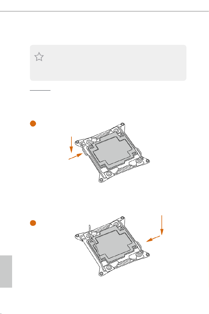
2.1 Installing the CPU
CAUTION:
Please note that X99 platform is only compatible with the LGA 2011-3 sock et, which is
incompatible with the LGA 2011 socket (for X79 platform).
1. Before you insert the -Pin CPU into the socket, please check if the is on 2011-3 PnP cap
the socket, if the CPU surface is unclean, or if there are any in the socket. Do bent pins
not force to insert the CPU into the socket if above situation is found. Otherwise, the CPU
will be seriously damaged.
2. Unplug all power cables before installing the CPU.
A
B
A
B
1
2

English
X99 Taichi
15
4
A
3
B
5

English
16
Please save and replace the cover if the processor is removed. e cover must be placed if
you wish to return the motherboard for aer service.
6
A
B
8
B
7
A

English
X99 Taichi
17
2.2 Installing the CPU Fan and Heatsink
CPU_
FAN
1 2

English
18
2.3 Installation of Memory Modules (DIMM)
is motherboard provides eight 288-pin DDR4 (Double Data Rate 4) DIMM slots, and
supports Quad Channel Memory Technology.
Quad Channel Memory Conguration
Priority 1 2
DDR4_A1 Populated Populated
DDR4_A2 Populated
DDR4_B1 Populated Populated
DDR4_B2 Populated
DDR4_C1 Populated Populated
DDR4_C2 Populated
DDR4_D1 Populated Populated
DDR4_D2 Populated
• Due to Intel® CPU spec denition, please install the memory modules on DDR4_A1,
DDR4_B1, DDR4_C1 and DDR4_D1 for rst priority. If the four DDR4 DIMM slots
above are fully installed, and you want to use more than four memory modules, please
install the other memory modules from le to right (from DDR4_A2, DDR4_B2,
DDR4_D2 to DDR4_C2.)
• If only two memory modules are installed in the DDR4 DIMM slots, then Dual
Channel Memory Technology is activated. If three memory modules are installed, then
Triple Channel Memory Technology is activated. If more than four memory modules
are installed in the DDR4 DIMM slots, then Quad Channel Memory Technology is
activated.
1. For quad channel conguration, you always need to install identical (the same brand,
speed, size and chip-type) DDR4 DIMM pairs.
2. It is not allowed to install a DDR, DDR2 or DDR3 memory module into a DDR4 slot;
otherwise, this motherboard and DIMM may be damaged.
3. e DIMM only ts in one correct orientation. It will cause permanent damage to the
motherboard and the DIMM if you force the DIMM into the slot at incorrect orientation.

English
X99 Taichi
19
1
2
3

English
20
2.4 Expansion Slots (PCI Express Slots)
ere are 5 PCI Express slots on the motherboard.
PCIe slots:
PCIE1 (PCIe 2.0 p26-x1 slot) is used for PCI Express p26-x1 lane width cards.
*Please install the memory modules before installing a PCIe card into the PCIE1 slot.
PCIE2 (PCIe 3.0 x16 slot) is used for PCI Express x16 lane width graphics cards.
PCIE3 (PCIe 2.0 p26-x1 slot) is used for PCI Express p26-x1 lane width cards.
PCIE4 (PCIe 3.0 x16 slot) is used for PCI Express x16 lane width graphics cards.
PCIE5 (PCIe 3.0 x16 slot) is used for PCI Express p26-x8 lane width graphics cards.
PCIe Slot Congurations (For CPU with 40 PCIe lanes)
PCIE1 PCIE2 PCIE4 PCIE5PCIE3
Single Graphics Card N/A N/A N/A N/Ax16
Two Graphics Cards in
CrossFireXTM or SLITM
Mode
N/A N/A N/Ax16 x16
ree Graphics Cards in
3-Way CrossFireXTM Mode
or 3-Way SLITM Mode
N/A N/Ax16 x8 x8
Before installing an expansion card, please make sure that the power supply is switched o
or the power cord is unplugged. Please read the documentation of the expansion card and
make necessary hardware settings for the card before you start the installation.

English
22
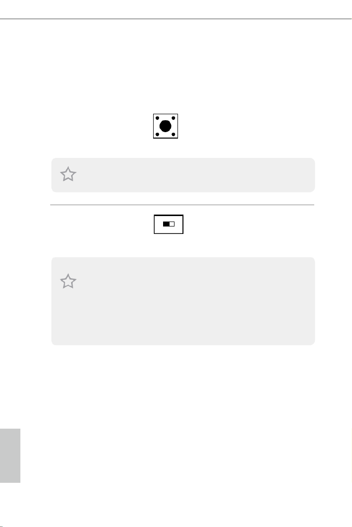
2.5 Jumpers Setup
e illustration shows how jumpers are setup. When the jumper cap is placed on
the pins, the jumper is “Short”. If no jumper cap is placed on the pins, the jumper
is “Open”. e illustration shows a 3-pin jumper whose pin1 and pin2 are “Short”
when a jumper cap is placed on these 2 pins.
Clear CMOS Jumper
(CLRCMOS1)
(see p.7, No. 26)
CLRCMOS1 allows you to clear the data in CMOS. To clear and reset the system
parameters to default setup, please turn o the computer and unplug the power
cord from the power supply. Aer waiting for 15 seconds, use a jumper cap to
short pin2 and pin3 on CLRCMOS1 for 5 seconds. However, please do not clear
the CMOS right aer you update the BIOS. If you need to clear the CMOS when
you just nish updating the BIOS, you must boot up the system rst, and then shut
it down before you do the clear-CMOS action. Please be noted that the password,
date, time, and user default prole will be cleared only if the CMOS battery is
removed.
Clear CMOSDefault
e Clear CMOS Switch has the same function as the Clear CMOS jumper.

English
X99 Taichi
23
2.6 Onboard Headers and Connectors
System Panel Header
(9-pin PANEL1)
(see p.7, No. 23)
Connect the power switch,
reset switch and system
status indicator on the
chassis to this header
according to the pin
assignments below. Note
the positive and negative
pins before connecting the
cables.
Power LED and Speaker
Header
(7-pin SPK_PLED1)
(see p.7, No. 24)
Please connect the
chassis power LED and
the chassis speaker to this
header.
GN D
R #ESET
PW RBT N#
PL E D-
PL E D+
GN D
HDL E D-
HDL E D+
1
GN D
PWRBTN (Power Switch):
Connect to the power switch on the chassis front panel. You may congure the way to turn
o your system using the power switch.
RESET (Reset Switch):
Connect to the reset switch on the chassis front panel. Press the reset switch to restart the
computer if the computer freezes and fails to perform a normal restart.
PLED (System Power LED):
Connect to the power status indicator on the chassis front panel. e LED is on when the
system is operating. e LED keeps blinking when the system is in S1/S3 sleep state. e
LED is o when the system is in S4 sleep state or powered o (S5).
HDLED (Hard Drive Activity LED):
Connect to the hard drive activity LED on the chassis front panel. e LED is on when the
hard drive is reading or writing data.
e front panel design may dier by chassis. A front panel module mainly consists of power
switch, reset switch, power LED, hard drive activity LED, speaker and etc. When connect-
ing your chassis front panel module to this header, make sure the wire assignments and the
pin assignments are matched correctly.
Onboard headers and connectors are NOT jumpers. Do NOT place jumper caps over these
headers and connectors. Placing jumper caps over the headers and connectors will cause
permanent damage to the motherboard.
1
+5 V
DUMM Y
PLED+
PLED+
PLED-
DUMM Y
SPEAKER

English
24
Serial ATA3 Connectors
(SSATA3_0_1:
see p.7, No. 14)
(SSATA3_2:
see p.7, No. 13)
(SSATA3_3:
see p.7, No. 11)
(SATA3_0_3:
see p.7, No. 15)
(SATA3_1_4:
see p.7, No. 16)
(SATA3_2_5:
see p.7, No. 17)
ese ten SATA3
connectors support SATA
data cables for internal
storage devices with up to
6.0 Gb/s data transfer rate.
* e SSATA3_3 connector
is shared with the M2_1 ;
the SSATA3_2 connector
is shared with the M2_2.
* RAID is supported on
SATA3_0 ~ SATA3_5
ports only.
Serial ATA Express
Connector
(SATAE_1:
see p.7, No. 18)
Please connect either SATA
or PCIe storage devices
to this connector. e
SATA Express connector is
shared with the SATA3_4
and the SATA3_5.
*e SATA Express
interface is a combination
of SATAE_1, SATA3_5,
and SATA3_4.
USB 2.0 Headers
(9-pin USB3_4)
(see p.7, No. 19)
(9-pin USB5_6)
(see p.7, No. 20)
Besides three USB 2.0 ports
on the I/O panel, there
are two headers and one
port on this motherboard.
Each USB 2.0 header can
support two ports.
DUMMY
GND
GND
P+
P-
U RSB _PW
P+
P-
U RSB _PW
1
SATA3_5SATAE_1 SATA3_4
SATA3_0
SATA3_3
SATA3_2
SATA3_5
SATA3_1
SATA3_4
SSATA3_0
SSATA3_1
SSATA3_3 SSATA3_2

English
X99 Taichi
25
USB 3.0 Header
(19-pin USB3_1_2)
(see p.7, No. 10)
ere is one USB 3.0 header
on this motherboard.
is USB 3.0 header can
support two ports.
Front Panel Audio Header
(9-pin HD_AUDIO1)
(see p.7, No. 27)
is header is for
connecting audio devices
to the front audio panel.
Chassis Fan Connectors
(4-pin CHA_FAN1)
(see p.7, No. 28)
(3-pin CHA_FAN2)
(see p.7, No. 12)
(3-pin CHA_FAN3)
(see p.7, No. 9)
Please connect fan cables
to the fan connectors and
match the black wire to
the ground pin. CHA_
FAN fan speed can be
controlled through UEFI
or A-Tuning.
J_SENSE
OUT2_L
1
MIC_RET
PRESENCE#
GND
OUT2_R
MIC2_R
MIC2_L
OUT_RET
1. High Denition Audio supports Jack Sensing, but the panel wire on the chassis must sup-
port HDA to function correctly. Please follow the instructions in our manual and chassis
manual to install your system.
2. If you use an AC’97 audio panel, please install it to the front panel audio header by the
steps below:
A. Connect Mic_IN (MIC) to MIC2_L.
B. Connect Audio_R (RIN) to OUT2_R and Audio_L (LIN) to OUT2_L.
C. Connect Ground (GND) to Ground (GND).
D. MIC_RET and OUT_RET are for the HD audio panel only. You don’t need to connect
them for the AC’97 audio panel.
E. To activate the front mic, go to the “FrontMic” Tab in the Realtek Control panel and
adjust “Recording Volume”.
1
In tA_ PB_ D+
Du m m y
In tA_ PB_ D-
GND
In tA_ PB_ SST X+
GND
In tA_ PB_ SST X-
In tA_ PB_ SSRX+
In tA_ PB_ SSRX-
VbusVbus
Vbus
In tA _ PA _ SS RX-
In tA _ PA _ SS RX+
GND
In tA _ PA _ SS T X-
In tA _ PA _ SS T X+
GND
In tA _ PA_D -
In tA _ PA_D +
GND
FAN_VOLTAGE
CHA_FAN_SPEED
FAN_ SPEED_CONTR
OL
GND
FA N_ VOLTA GE
CH A_ FAN_S PEED
FAN_S PEED_CONT RO L
GND
CH A_ FAN_S PEED
FAN_S PEED_CONT RO L
FA N_ VOLTA GE

English
26
CPU Fan Connectors
(4-pin CPU_FAN1)
(see p.7, No. 4)
is motherboard
provides a 4-Pin CPU fan
(Quiet Fan) connector. If
you plan to connect a 3-Pin
CPU fan, please connect it
to Pin 1-3.
CPU Optional/Water
Pump Fan Connector
(4-pin CPU_OPT/W_
PUMP)
(see p.7, No. 7)
is motherboard
provides a 4-Pin water
cooling CPU fan
connector. If you plan to
connect a 3-Pin CPU water
cooler fan, please connect
it to Pin 1-3.
ATX Power Connector
(24-pin ATXPWR1)
(see p.7, No. 8)
is motherboard
provides a 24-pin ATX
power connector. To use a
20-pin ATX power supply,
please plug it along Pin 1
and Pin 13.
ATX 12V Power
Connector
(8-pin ATX12V1)
(see p.7, No. 3)
is motherboard
provides an 8-pin ATX
12V power connector. To
use a 4-pin ATX power
supply, please plug it along
Pin 1 and Pin 5.
Serial Port Header
(9-pin COM1)
(see p.7, No. 21)
is COM1 header
supports a serial port
module.
FA N_V OLTAGE
GND
CP U_ N_SPEEFA D
FA LN_ SPEED_C ON TRO
1 2 3 4
FA N_V OLTAGE
GND
CP U_ N_SPEEFA D
FA LN_ SPEED_C ON TRO
1 2 3 4
12
1
24
13
4 1
8 5
CC TS # 1
RR TS # 1
DD SR# 1
DD TR # 1
RRXD1
GND
TTXD1
DDCD#1
1
RR I# 1

English
X99 Taichi
27
TPM Header
(17-pin TPMS1)
(see p.7, No. 22)
is connector supports Trusted
Platform Module (TPM) system,
which can securely store keys,
digital certicates, passwords, and
data. A TPM system also helps en-
hance network security, protects
digital identities, and ensures
platform integrity.
1
GN D
SMB _D ATA _M AI N
LAD2
LAD1
GN D
S_PWRDWN #
SERIRQ #
GND
P CIC L K
P CI RS T #
LAD3
+ 3 V
LAD0
+3VS B
GN D
FRAM E SMB _C LK _ MA IN
English
28
2.7 Smart Switches
e motherboard has two smart switches: Clear CMOS Switch and one BIOS
Selection Switch, allowing users to quickly clear the CMOS values or boot from
dierent BIOS.
Clear CMOS Switch
(CLRCBTN1)
(see p.9, No. 15)
Clear CMOS Switch
allows users to quickly
clear the CMOS values.
BIOS Selection Switch
(BIOS_SEL1)
(see p.7, No. 25)
BIOS Selection Switch allows
the system to boot from either
BIOS A or BIOS B.
is function is workable only when you power o your computer and unplug the power
supply.
A B
is motherboard has two BIOS chips, a primary BIOS (BIOS_A) and a backup BIOS (BIOS_
B), which enhances the safety and stability of your system. Normally, the system will work
on the primary BIOS. However, if the primary BIOS is corrupted or damaged, just ip the
BIOS Selection Switch to “B”, then the backup BIOS will take over on the next system boot.
Aer that, use “Secure Backup UEFI” in the UEFI Setup Utility to duplicate a working copy
of the BIOS les to the primary BIOS to ensure normal system operation. For safety issues,
users are not able to update the backup BIOS manually. Users may refer to the BIOS LEDs
(BIOS_A_LED or BIOS_B_LED) to identify which BIOS is currently activated.

English
X99 Taichi
29
2.8 Dr. Debug
Dr. Debug is used to provide code information, which makes troubleshooting even
easier. Please see the diagrams below for reading the Dr. Debug codes.
Code Description
00 Please check if the CPU is installed correctly and then clear
CMOS.
0d Problem related to memory, VGA card or other devices.
Please clear CMOS, re-install the memory and VGA card,
and remove other USB, PCI devices.
01 - 54
(except 0d),
5A- 60
Problem related to memory. Please re-install the CPU and
memory then clear CMOS. If the problem still exists, please
install only one memory module or try using other memory
modules.
55 e Memory could not be detected. Please re-install the
memory and CPU. If the problem still exists, please install
only one memory module or try using other memory
modules.
61 - 91 Chipset initialization error. Please press reset or clear
CMOS.
92 - 99 Problem related to PCI-E devices. Please re-install PCI-E
devices or try installing them in other slots. If the problem
still exists, please remove all PCI-E devices or try using
another VGA card.
A0 - A7 Problem related to IDE or SATA devices. Please re-install
IDE and SATA devices. If the problem still exists, please
clear CMOS and try removing all SATA devices.
b0 Problem related to memory. Please re-install the CPU and
memory. If the problem still exists, please install only one
memory module or try using other memory modules.

English
30
b4 Problem related to USB devices. Please try removing all
USB devices.
b7 Problem related to memory. Please re-install the CPU and
memory then clear CMOS. If the problem still exists, please
install only one memory module or try using other memory
modules.
d6 e VGA could not be recognized. Please clear CMOS and
try re-installing the VGA card. If the problem still exists,
please try installing the VGA card in other slots or use other
VGA cards.
d7 e Keyboard and mouse could not be recognized. Please
try re-installing the keyboard and mouse.
d8 Invalid Password.
FF Please check if the CPU is installed correctly and then clear
CMOS.

English
X99 Taichi
31
2.9 SLITM , 3-Way SLITMand Quad SLITM Operation Guide
is motherboard supports NVIDIA
® SLITM , 3-Way SLITM and Quad SLITM (Scalable
Link Interface) technolog y that allows you to install up to three identical PCI
Express p37-x16 graphics cards. Currently, NVIDIA
® SLITM and Quad SLITM technology
supports Windows® 7 / 7 64-bit / 8 / 8 64-bit / 8.1 / 8.1 64-bit / 10 / 10 64-bitOS.
2.9.1 Installing Two SLITM-Ready Graphics Cards
Step 1
Insert one graphics card into PCIE2 slot
and the other graphics card to PCIE4 slot.
Make sure that the cards are properly
seated on the slots.
Step 2
If required, connect the auxiliary power
source to the PCI Express graphics cards.
Requirements
1. You should only use identical SLITM-ready graphics cards that are NVIDIA®
certied.
2. Make sure that your graphics card driver supports NVIDIA
® SLITM technology. Download
the drivers from the NVIDIA® website: www.nvidia.com
3. Make sure that your power supply unit (PSU) can provide at least the minimum power
your system requires. It is recommended to use a NVIDIA
® certied PSU. Please refer to
the NVIDIA® website for details.

English
32
Step 3
Align and insert the ASRock SLI_
Bridge_2S Card/ASRock SLI_HB_
Bridge_2S Card to the goldngers on each
graphics card. Make sure the ASRock
SLI_Bridge_2S Card/ASRock SLI_HB_
Bridge_2S Card is rmly in place.
* Whether to use ASRock SLI_Bridge_2S
Card or ASRock SLI_HB_Bridge_2S
Card depends on the type of graphics card
you use.
Step 4
Connect a VGA cable or a DVI cable to the
monitor connector or the DVI connector of
the graphics card that is inserted to PCIE2
slot.
ASRock SLI_Bridge_2S Card
ASRock SLI_HB_Bridge_2S Card
or
SLI_Bridge_2S Card
SLI_HB_Bridge_2S Card

English
X99 Taichi
33
2.9.2 Installing Three SLITM-Ready Graphics Cards
Step 1
Insert one graphics card into PCIE2 slot,
another graphics card to PCIE4 slot, and
the other graphics card to PCIE5 slot.
Make sure that the cards are properly
seated on the slots.
Step 2
Connect the auxiliary power source to the
PCI Express graphics card. Please make
sure that both power connectors on the
PCI Express graphics card are connected.
Repeat this step on the three graphics
cards.
Step 3
Align and insert the ASRock 3-Way SLI-
2S1S Bridge Card to the goldngers on
each graphics card. Make sure the ASRock
3-Way SLI-2S1S Bridge Card is rmly in
place.
3-Way SLI-2S1S Bridge Card
3-Way
SLI-
2S1S

English
34
Step 4
Connect a VGA cable or a DVI cable to the
monitor connector or the DVI connector of
the graphics card that is inserted to PCIE2
slot.

English
X99 Taichi
35
2.9.3 Driver Installation and Setup
Install the graphics card drivers to your system. Aer that, you can enable the
Multi-Graphics Processing Unit (GPU) in the NVIDIA® nView system tray utility.
Please follow the below procedures to enable the multi-GPU.
Step 1
Double-click the NVIDIA Control Panel
icon in the Windows® system tray.
Step 2
In the le pane, click Set SLI and PhysX
conguration Maximize 3D . en select
performance Apply and click .
Step 3
Reboot your system.
English
36
2.10 CrossFireXTM, 3-Way CrossFireXTM and Quad CrossFireXTM
Operation Guide
is motherboard supports CrossFireXTM, 3-way CrossFireXTM and Quad
CrossFireXTM that allows you to install up to three identical PCI Express
x16 graphics cards. Currently CrossFireXTM, 3-way CrossFireXTM and Quad
CrossFireXTM are supported with Windows
® 7 / 7 64-bit / 8 / 8 64-bit / 8.1 / 8.1 64-
bit / 10 / 10 64-bit OS.
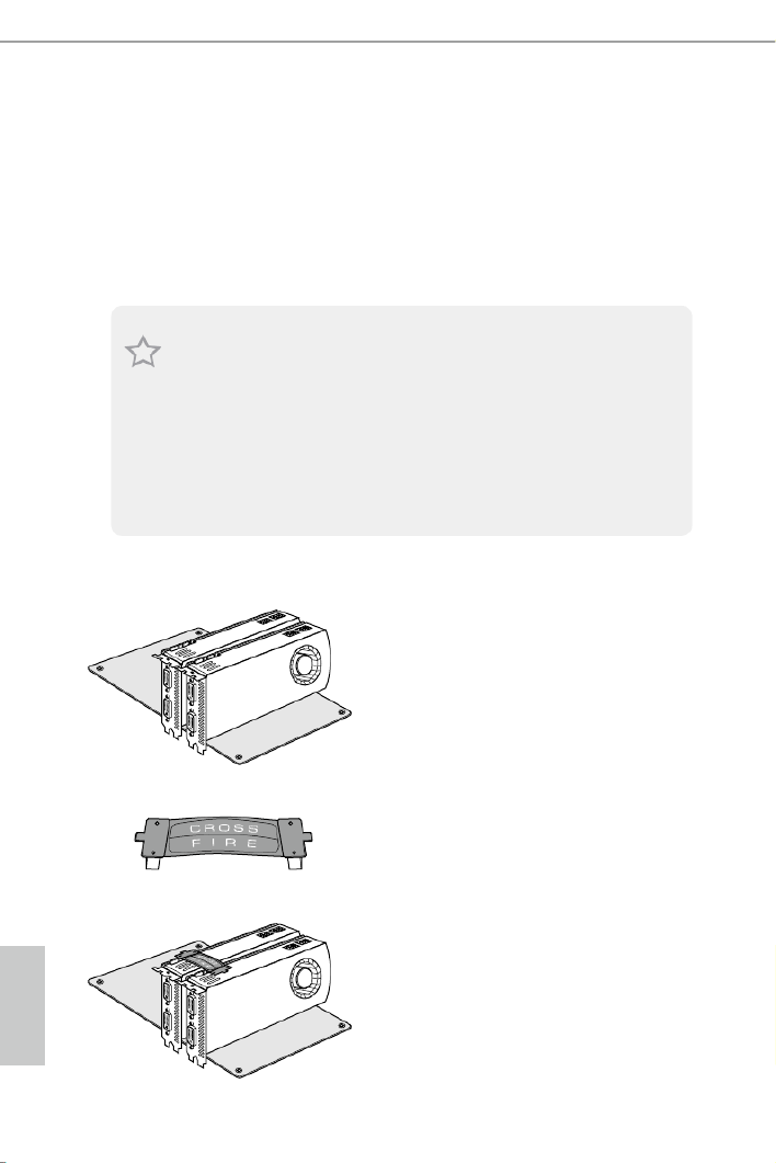
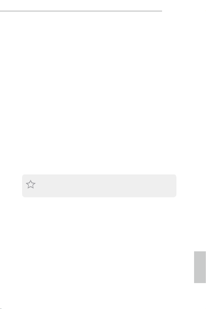
2.10.1 Installing Two CrossFireXTM-Ready Graphics Cards
Step 1
Insert one graphics card into PCIE2 slot
and the other graphics card to PCIE4 slot.
Make sure that the cards are properly
seated on the slots.
Step 2
Connect two graphics cards by installing
a CrossFire Bridge on the CrossFire Bridge
Interconnects on the top of the graphics
cards. (e CrossFire Bridge is provided
with the graphics card you purchase, not
bundled with this motherboard. Please
refer to your graphics card vendor for
details.)
1. You should only use identical CrossFireX
TM-ready graphics cards that are AMD certied.
2. Make sure that your graphics card driver supports AMD CrossFireXTM technology.
Download the drivers from the AMD’s website: www.amd.com
3. Make sure that your power supply unit (PSU) can provide at least the minimum power
your system requires. It is recommended to use a AMD certied PSU. Please refer to the
AMD’s website for details.
4. If you pair a 12-pipe CrossFireXTM
Edition card with a 16-pipe card, both cards will oper-
ate as 12-pipe cards while in CrossFireXTM
mode.
5. Dierent CrossFireXTM cards may require dierent methods to enable CrossFireXTM.
Please refer to AMD graphics card manuals for detailed installation guide.
CrossFire Bridge

English
X99 Taichi
37
Step 3
Connect a VGA cable or a DVI cable to the
monitor connector or the DVI connec-
tor of the graphics card that is inserted to
PCIE2 slot.

English
38
2.10.2 Installing Three CrossFireXTM-Ready Graphics Cards
Step 1
Insert one graphics card into PCIE2 slot,
another graphics card to PCIE4 slot, and
the other graphics card to PCIE5 slot.
Make sure that the cards are properly
seated on the slots.
Step 2
Use one CrossFire Bridge to connect
the graphics cards on PCIE2 and PCIE4
slots, and use the other CrossFire Bridge
to connect the graphics cards on PCIE4
and PCIE5 slots. (e CrossFire Bridge
is provided with the graphics card
you purchase, not bundled with this
motherboard. Please refer to your graphics
card vendor for details.)
Step 3
Connect a VGA cable or a DVI cable to the
monitor connector or the DVI connec-
tor of the graphics card that is inserted to
PCIE2 slot.
CrossFire Bridge

English
40
2.11 M.2_SSD (NGFF) Module Installation Guide
e M.2, also known as the Next Generation Form Factor (NGFF), is a small size and
versatile card edge connector that aims to replace mPCIe and mSATA. e Ultra M.2
Socket (M2) can accommodate either a M.2 SATA3 6.0 Gb/s module or a M.2 PCI Express
module up to Gen3 p46-x4 (32 Gb/s).
* e M2_1 connector is shared with the SSATA3_3; the M2_2 connector is shared with
the SSATA3_2.
* If you install CPU with 28 lanes, the M2_1 only supports SATA type M.2 module.
Installing the M.2_SSD (NGFF) Module
e following is an example of installing M.2_SSD (NGFF) module into the M2_2.
Step 1
Prepare a M.2_SSD (NGFF) module
and the screw.
3
2
4
5
BCDE A
1
Step 2
Depending on the PCB type and
length of your M.2_SSD (NGFF)
module, nd the corresponding nut
location to be used.
No. 1 2 3 4 5
Nut Location A B C D E
PCB Length 3cm 4.2cm 6cm 8cm 11cm
Module Type Type2230 Type 2242 Type2260 Type 2280 Type 22110

English
X99 Taichi
41
BCDE A
Step 3
Move the stando based on the
module type and length.
e stando is placed at the nut
location D by default. Skip Step 3
and 4 and go straight to Step 5 if you
are going to use the default nut.
Otherwise, release the stando by
hand.
BCDE A
Step 4
Peel o the yellow protective lm on
the nut to be used. Hand tighten the
stando into the desired nut location
on the motherboard.
BC A
ABCDE
Step 5
Align and gently insert the M.2
(NGFF) SSD module into the M.2
slot. Please be aware that the M.2
(NGFF) SSD module only ts in one
orientation.
DE
Step 6
Tighten the screw with a screwdriver
to secure the module into place.
Please do not overtighten the screw
as this might damage the module.

English
42
M.2_SSD (NGFF) Module Support List
For the latest updates of M.2_SSD (NFGG) module support list, please visit our website for
details: http://www.asrock.com
Vendor Size Interface Length P/N
ADATA 128GB AXNS381E-128GM-BSATA3 2280
ADATA 256GB SATA3 2280 AXNS381E-256GM-B
ADATA 32GB SATA3 2230 AXNS330E-32GM-B
Crucial 120GB SATA3 2280 CT120M500SSD4
Crucial 240GB SATA3 2280 CT240M500SSD4
Intel Intel SSDSCKGW080A401/80G80GB SATA3 2280
Kingston 120GB SATA3 2280 SM2280S3
Kingston 480GB SH2280S3/480GPCIe2 x4 2280
Plextor PCIe256GB 2280 PX-G256M6e
Plextor PCIe512GB 2280 PX-G512M6e
Samsung 256GB SM951 (MZHPV256HDGL)PCIe3 x4 2280
Samsung 512GB SM951 (MZHPV512HDGL)PCIe3 x4 2280
Samsung 512GB PCIe x4 2280 XP941-512G (MZHPU512HCGL)
SanDisk 128GB PCIe 2260 SD6PP4M-128G
SanDisk 256GB PCIe 2260 SD6PP4M-256G
Team 128GB SATA3 2242 TM4PS4128GMC105
Team 128GB SATA3 2280 TM8PS4128GMC105
Team 256GB SATA3 2280 TM8PS4256GMC105
Team 256GB SATA3 2242 TM4PS4256GMC105
Transcend 256GB SATA3 2242 TS256GMTS400
Transcend 512GB SATA3 2280 TS512GMTS800
Transcend 512GB SATA3 2260 TS512GMTS600
English
X99 Taichi
43
Chapter 3 Software and Utilities Operation
3.1 Installing Drivers
e Support CD that comes with the motherboard contains necessary drivers and
useful utilities that enhance the motherboard’s features.
Running The Support CD
To begin using the support CD, insert the CD into your CD-ROM drive. e CD
automatically displays the Main Menu if “AUTORUN” is enabled in your computer.
If the Main Menu does not appear automatically, locate and double click on the le
“ASRSETUP.EXE” in the Support CD to display the menu.
Drivers Menu
e drivers compatible to your system will be auto-detected and listed on the
support CD driver page. Please click Install All or follow the order from top to
bottom to install those required drivers. erefore, the drivers you install can work
properly.
Utilities Menu
e Utilities Menu shows the application soware that the motherboard supports.
Click on a specic item then follow the installation wizard to install it.
To improve Windows 7 compatibility, please download and install the following hot x
provided by Microso.
“KB2720599”: http://support.microso.com/kb/2720599/en-us

English
44
3.2 A-Tuning
A-Tuning is ASRock’s multi purpose soware suite with a new interface, more new
features and improved utilities.
3.2.1 Installing A-Tuning
A-Tuning can be downloaded from ASRock Live Update & APP Shop. Aer the
installation, you will nd the icon “A-Tuning“ on your desktop. Double-click the
“A-Tuning A-Tuning“ icon, main menu will pop up.
3.2.2 Using A-Tuning
ere are six sections in A-Tuning main menu: Operation Mode, OC Tweaker,
System Info, FAN-Tastic Tuning, Tech Service and Settings.
Operation Mode
Choose an operation mode for your computer.
English
X99 Taichi
45
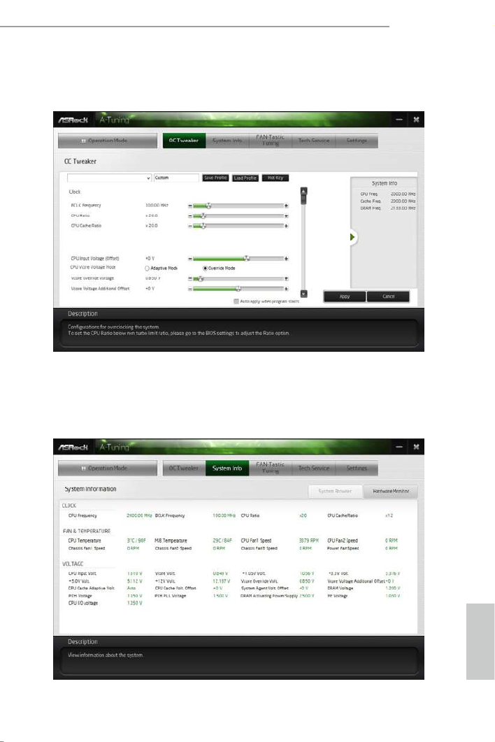
OC Tweaker
Congurations for overclocking the system.
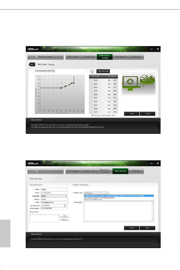
System Info
View information about the system.
*e System Browser tab may not appear for certain models.
English
46
FAN-Tastic Tuning
Congure up to ve dierent fan speeds using the graph. e fans will automatically shi
to the next speed level when the assigned temperature is met.
Tech Service
Contact Tech Service if you have problems with your computer. Please leave your
contact information along with details of the problem.

English
X99 Taichi
47
Settings
Congure ASRock A-Tuning. Click to select "Auto run at Windows Startup" if you
want A-Tuning to be launched when you start up the Windows operating system.
Termékspecifikációk
| Márka: | Asrock |
| Kategória: | alaplap |
| Modell: | X99 Taichi |
Szüksége van segítségre?
Ha segítségre van szüksége Asrock X99 Taichi, tegyen fel kérdést alább, és más felhasználók válaszolnak Önnek
Útmutatók alaplap Asrock

25 Március 2025
13 Január 2025
13 Január 2025
12 Január 2025
2 Január 2025
28 December 2024
14 Október 2024
10 Október 2024
4 Október 2024
3 Október 2024
Útmutatók alaplap
- alaplap Sharkoon
- alaplap Gigabyte
- alaplap Asus
- alaplap Supermicro
- alaplap Biostar
- alaplap MSI
- alaplap NZXT
- alaplap ECS
- alaplap Evga
- alaplap Intel
- alaplap Foxconn
- alaplap Advantech
- alaplap Elitegroup
- alaplap EPoX
Legújabb útmutatók alaplap

9 Április 2025
9 Április 2025
3 Április 2025
3 Április 2025
3 Április 2025
3 Április 2025
2 Április 2025
2 Április 2025

31 Március 2025
27 Március 2025