Használati útmutató Asrock H310CM-HG4
Olvassa el alább 📖 a magyar nyelvű használati útmutatót Asrock H310CM-HG4 (72 oldal) a alaplap kategóriában. Ezt az útmutatót 7 ember találta hasznosnak és 2 felhasználó értékelte átlagosan 4.5 csillagra
Oldal 1/72


Version 1.0
Published April 2019
Copyright©2019 ASRock INC. All rights reserved.
Copyright Notice:
No part of this documentation may be reproduced, transcribed, transmitted, or
translated in any language, in any form or by any means, except duplication of
documentation by the purchaser for backup purpose, without written consent of
ASRock Inc.
Products and corporate names appearing in this documentation may or may not
be registered trademarks or copyrights of their respective companies, and are used
only for identication or explanation and to the owners’ benet, without intent to
infringe.
Disclaimer:
Specications and information contained in this documentation are furnished for
informational use only and subject to change without notice, and should not be
constructed as a commitment by ASRock. ASRock assumes no responsibility for
any errors or omissions that may appear in this documentation.
With respect to the contents of this documentation, ASRock does not provide
warranty of any kind, either expressed or implied, including but not limited to
the implied warranties or conditions of merchantability or tness for a particular
purpose.
In no event shall ASRock, its directors, ocers, employees, or agents be liable for
any indirect, special, incidental, or consequential damages (including damages for
loss of prots, loss of business, loss of data, interruption of business and the like),
even if ASRock has been advised of the possibility of such damages arising from any
defect or error in the documentation or product.
is device complies with Part 15 of the FCC Rules. Operation is subject to the following
two conditions:
(1) this device may not cause harmful interference, and
(2) this device must accept any interference received, including interference that
may cause undesired operation.
CALIFORNIA, USA ONLY
e Lithium battery adopted on this motherboard contains Perchlorate, a toxic substance
controlled in Perchlorate Best Management Practices (BMP) regulations passed by the
California Legislature. When you discard the Lithium battery in California, USA, please
follow the related regulations in advance.
“Perchlorate Material-special handling may apply, see www.dtsc.ca.gov/hazardouswaste/
perchlorate”
ASRock Website: http://www.asrock.com

AUSTRALIA ONLY
Our goods come with guarantees that cannot be excluded under the Australian
Consumer Law. You are entitled to a replacement or refund for a major failure and
compensation for any other reasonably foreseeable loss or damage caused by our
goods. You are also entitled to have the goods repaired or replaced if the goods fail
to be of acceptable quality and the failure does not amount to a major failure. If
you require assistance please call ASRock Tel : +886-2-28965588 ext.123 (Standard
International call charges apply)
e terms HDMI® and HDMI High-Denition Multimedia Interface, and the
HDMI logo are trademarks or registered trademarks of HDMI Licensing LLC in the
United States and other countries.

Contents
Chapter 1 Introduction 1
1.1 Package Contents 1
1.2 Specications 2
1.3 Motherboard Layout 6
1.4 I/O Panel 8
Chapter 2 Installation 10
2.1 Installing the CPU 11
2.2 Installing the CPU Fan and Heatsink 14
2.3 Installing Memory Modules (DIMM) 15
2.4 Expansion Slots (PCI Express Slots) 17
2.5 Onboard Headers and Connectors 18
Chapter 3 Software and Utilities Operation 22
3.1 Installing Drivers 22
3.2 A-Tuning 23
3.3 ASRock Live Update & APP Shop 26
3.3.1 UI Overview 26
3.3.2 Apps 27
3.3.3 BIOS & Drivers 30
3.3.4 Setting 31
Chapter 4 UEFI SETUP UTILITY 32
4.1 Introduction 32
4.2 EZ Mode 33

4.3 Advanced Mode 34
4.3.1 UEFI Menu Bar 34
4.3.2 Navigation Keys 35
4.4 Main Screen 36
4.5 OC Tweaker Screen 37
4.6 Advanced Screen 46
4.6.1 CPU Conguration 47
4.6.2 Chipset Conguration 49
4.6.3 Storage Conguration 51
4.6.4 Super IO Conguration 52
4.6.5 ACPI Conguration 53
4.6.6 USB Conguration 54
4.6.7 Trusted Computing 55
4.7 Tools 56
4.8 Hardware Health Event Monitoring Screen 58
4.9 Security Screen 60
4.10 Boot Screen 61
4.11 Exit Screen 64


English
1
H310CM-HG4
Chapter 1 Introduction
ank you for purchasing ASRock H310CM-HG4 motherboard, a reliable
motherboard produced under ASRock’s consistently stringent quality control.
It delivers excellent performance with robust design conforming to ASRock’s
commitment to quality and endurance.
In this documentation, Chapter 1 and 2 contains the introduction of the
motherboard and step-by-step installation guides. Chapter 3 contains the operation
guide of the soware and utilities. Chapter 4 contains the conguration guide of
the BIOS setup.
1.1 Package Contents
• ASRock H310CM-HG4 Motherboard (Micro ATX Form Factor)
• ASRock H310CM-HG4 Quick Installation Guide
• ASRock H310CM-HG4 Support CD
• 1 x I/O Panel Shield
• 2 x Serial ATA (SATA) Data Cables (Optional)
Because the motherboard specications and the BIOS soware might be updated, the
content of this documentation will be subject to change without notice. In case any modi-
cations of this documentation occur, the updated version will be available on ASRock’s
website without further notice. If you require technical support related to this mother-
board, please visit our website for specic information about the model you are using. You
may nd the latest VGA cards and CPU support list on ASRock’s website as well. ASRock
website http://www.asrock.com.

English
4
Connector • 1 x TPM Header
• 1 x Chassis Intrusion and Speaker Header
• 1 x CPU Fan Connector (4-pin)
* e CPU Fan Connector supports the CPU fan of maximum
1A (12W) fan power.
• 1 x Chassis/Water Pump Fan Connector (4-pin) (Smart Fan
Speed Control)
* e Chassis/Water Pump Fan supports the water cooler fan of
maximum 2A (24W) fan power.
* CHA_FAN1/WP can auto detect if 3-pin or 4-pin fan is in use.
• 1 x 24 pin ATX Power Connector
• 1 x 8 pin 12V Power Connector
• 1 x Front Panel Audio Connector
• 1 x USB 2.0 Header (Supports 2 USB 2.0 ports) (Supports
ESD Protection)
• 1 x USB 3.2 Gen1 Header (Supports 2 USB 3.2 Gen1 ports)
(Supports ESD Protection)
BIOS
Feature
• AMI UEFI Legal BIOS with multilingual GUI support
• ACPI 6.0 Compliant wake up events
• SMBIOS 2.7 Support
• DRAM, PCH 1.05V Voltage Multi-adjustment
Hardware
Monitor
• Temperature Sensing: CPU, Chassis/Water Pump Fans
• Fan Tachometer: CPU, Chassis/Water Pump Fans
• Quiet Fan (Auto adjust chassis fan speed by CPU
temperature): CPU, Chassis/Water Pump Fans
• Fan Multi-Speed Control: CPU, Chassis/Water Pump Fans
• CASE OPEN detection
• Voltage monitoring: +12V, +5V, +3.3V, CPU Vcore
OS • Microso® Windows® 10 64-bit
Certica-
tions
• FCC, CE
• ErP/EuP ready (ErP/EuP ready power supply is required)

English
5
H310CM-HG4
* For detailed product information, please visit our website: http://www.asrock.com
Please realize that there is a certain risk involved with overclocking, including adjusting
the setting in the BIOS, applying Untied Overclocking Technology, or using third-party
overclocking tools. Overclocking may aect your system’s stability, or even cause damage to
the components and devices of your system. It should be done at your own risk and expense.
We are not responsible for possible damage caused by overclocking.

English
7
H310CM-HG4
No. Description
1 ATX 12V Power Connector (ATX12V1)
2 CPU Fan Connector (CPU_FAN1)
3 2 x 288-pin DDR4 DIMM Slots (DDR4_A1, DDR4_B1)
4 Chassis/Water Pump Fan (CHA_FAN1/WP)
5 ATX Power Connector (ATXPWR1)
6 USB 3.2 Gen1 Header (USB3_3_4)
7 USB 2.0 Header (USB_5_6)
8 SATA3 Connector (SATA3_2)
9 SATA3 Connector (SATA3_3)
10 SATA3 Connector (SATA3_0)
11 SATA3 Connector (SATA3_1)
12 System Panel Header (PANEL1)
13 TPM Header (TPMS1)
14 Chassis Intrusion and Speaker Header (SPK_CI1)
15 Clear CMOS Pad (CLRMOS1)
16 Front Panel Audio Header (HD_AUDIO1)

English
8
1.4 I/O Panel
No. No.Description Description
1 USB 2.0 Ports (USB12) 6 USB 2.0 Ports (USB_34)
2 LAN RJ-45 Port* 7 USB 3.2 Gen1 Ports (USB3_12)
3 Line In (Light Blue)** 8 HDMI Port
4 Front Speaker (Lime)** 9 D-Sub Port
5 Microphone (Pink)** PS/2 Keyboard/Mouse Port10
10 6 589
1 2 4
7
3
English
9
H310CM-HG4
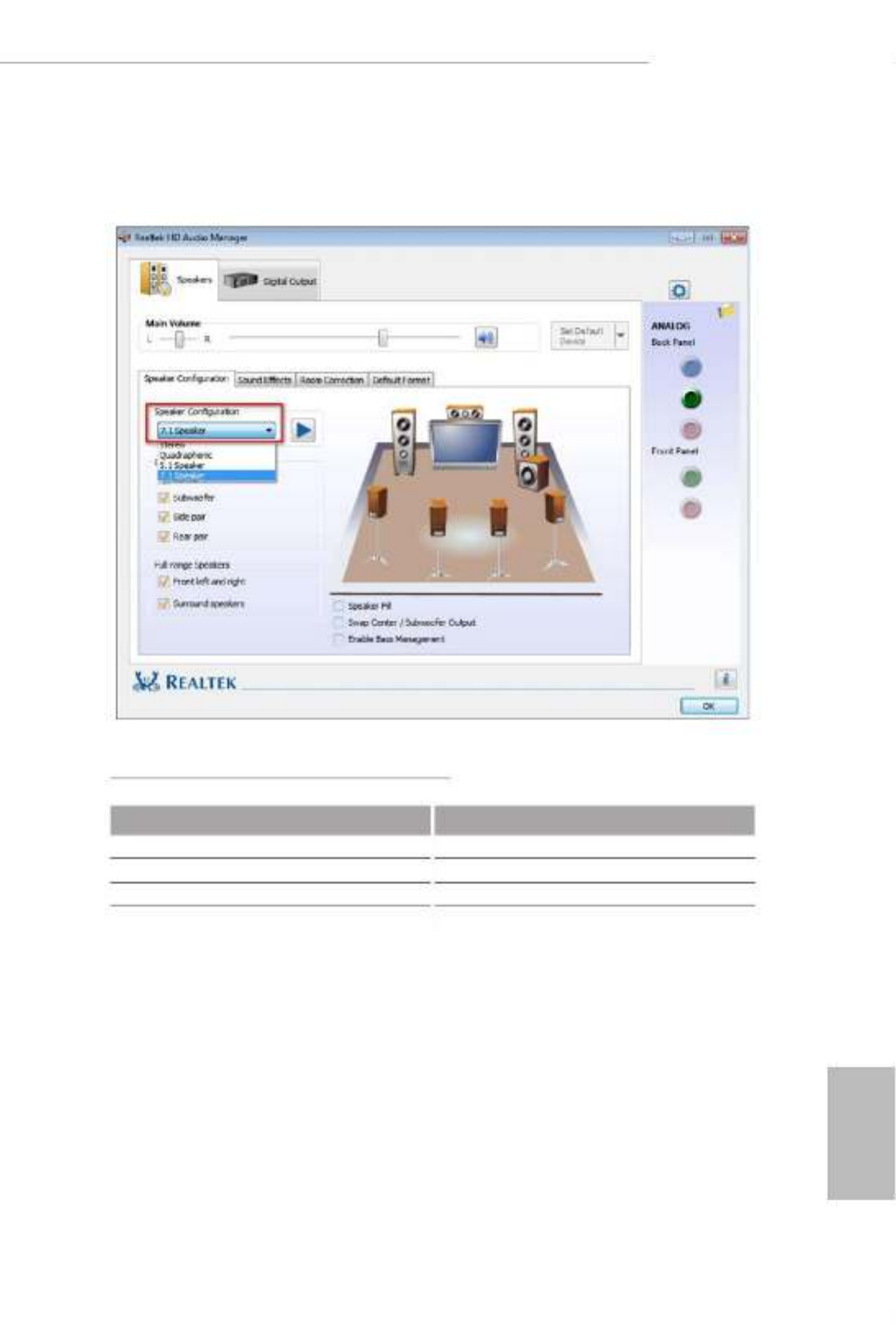
** To congure 7.1 CH HD Audio, it is required to use an HD front panel audio module and enable the multi-
channel audio feature through the audio driver.
Please set Speaker Conguration to “7.1 Speaker”in the Realtek HD Audio Manager.
Function of the Audio Ports in 7.1-channel Conguration:
Port Function
Light Blue (Rear panel) Rear Speaker Out
Lime (Rear panel) Front Speaker Out
Pink (Rear panel) Central /Subwoofer Speaker Out
Lime (Front panel) Side Speaker Out

English
10
is is a Micro ATX form factor motherboard. Before you install the motherboard,
study the conguration of your chassis to ensure that the motherboard ts into it.
Pre-installation Precautions
Take note of the following precautions before you install motherboard components
or change any motherboard settings.
• Make sure to unplug the power cord before installing or removing the motherboard
components. Failure to do so may cause physical injuries and damages to motherboard
components.
• In order to avoid damage from static electricity to the motherboard’s components,
NEVER place your motherboard directly on a carpet. Also remember to use a grounded
wrist strap or touch a safety grounded object before you handle the components.
• Hold components by the edges and do not touch the ICs.
• Whenever you uninstall any components, place them on a grounded anti-static pad or
in the bag that comes with the components.
• When placing screws to secure the motherboard to the chassis, please do not over-
tighten the screws! Doing so may damage the motherboard.
Chapter 2 Installation

English
11
H310CM-HG4
2.1 Installing the CPU
1. Before you insert the 1151-Pin CPU into the socket, please check if the is on the PnP cap
socket, if the CPU surface is unclean, or if there are any bent pins in the socket. Do not
force to insert the CPU into the socket if above situation is found. Otherwise, the CPU
will be seriously damaged.
2. Unplug all power cables before installing the CPU.
1
2
A
B

English
12
4
5
3

English
13
H310CM-HG4
Please save and replace the cover if the processor is removed. e cover must be placed if
you wish to return the motherboard for aer service.

English
14
2.2 Installing the CPU Fan and Heatsink
1 2
CPU_FAN
English
15
H310CM-HG4
2.3 Installing Memory Modules (DIMM)
is motherboard provides two 288-pin DDR4 (Double Data Rate 4) DIMM slots,
and supports Dual Channel Memory Technology.
e DIMM only ts in one correct orientation. It will cause permanent damage to
the motherboard and the DIMM if you force the DIMM into the slot at incorrect
orientation.
1. For dual channel conguration, you always need to install identical (the same
brand, speed, size and chip-type) DDR4 DIMM pairs.
2. It is unable to activate Dual Channel Memory Technology with only one memory
module installed.
3. It is not allowed to install a DDR, DDR2 or DDR3 memory module into a DDR4
slot; otherwise, this motherboard and DIMM may be damaged.

English
16
1
2
3

English
17
H310CM-HG4
2.4 Expansion Slots (PCI Express Slots)
ere are 2 PCI Express slots on the motherboard.
PCIe slots:
PCIE1 (PCIe 2.0 p23-x1 slot) is used for PCI Express p23-x1 lane width cards.
PCIE2 (PCIe 3.0 x16 slot) is used for PCI Express x16 lane width graphics cards.
Before installing an expansion card, please make sure that the power supply is
switched o or the power cord is unplugged. Please read the documentation of the
expansion card and make necessary hardware settings for the card before you start
the installation.

English
18
2.5 Onboard Headers and Connectors
System Panel Header
(9-pin PANEL1)
(see p.6, No. 12)
Connect the power
button, reset button and
system status indicator on
the chassis to this header
according to the pin
assignments below. Note
the positive and negative
pins before connecting
the cables.
GND R #ESET
PWRBTN
#
PLED-
PLED+
GND
HDLED-
HDLED+
1
GND
Onboard headers and connectors are NOT jumpers. Do NOT place jumper caps over
these headers and connectors. Placing jumper caps over the headers and connectors
will cause permanent damage to the motherboard.
PWRBTN (Power Button):
Connect to the power button on the chassis front panel. You may congure the way to turn
o your system using the power button.
RESET (Reset Button):
Connect to the reset button on the chassis front panel. Press the reset button to restart the
computer if the computer freezes and fails to perform a normal restart.
PLED (System Power LED):
Connect to the power status indicator on the chassis front panel. e LED is on when the
system is operating. e LED keeps blinking when the system is in S1/S3 sleep state. e
LED is o when the system is in S4 sleep state or powered o (S5).
HDLED (Hard Drive Activity LED):
Connect to the hard drive activity LED on the chassis front panel. e LED is on when the
hard drive is reading or writing data.
e front panel design may dier by chassis. A front panel module mainly consists of power
button, reset button, power LED, hard drive activity LED, speaker and etc. When connect-
ing your chassis front panel module to this header, make sure the wire assignments and the
pin assignments are matched correctly.

English
19
H310CM-HG4
Chassis Intrusion and
Speaker Header
(7-pin SPK_CI1)
(see p.6, No. 14)
Please connect the
chassis intrusion and the
chassis speaker to this
header.
Serial ATA3 Connectors
(SATA3_0:
see p.6, No. 10)
(SATA3_1:
see p.6, No. 11)
(SATA3_2:
see p.6, No. 8)
(SATA3_3:
see p.6, No. 9)
ese four SATA3
connectors support SATA
data cables for internal
storage devices with up to
6.0 Gb/s data transfer rate.
USB 2.0 Header
(9-pin USB_5_6)
(see p.6, No. 7)
ere is one USB
2.0 header on this
motherboard. is USB
2.0 header can support
two ports.
USB 3.2 Gen1 Header
(19-pin USB3_3_4)
(see p.6, No. 6)
ere is one header on
this motherboard. is
USB 3.2 Gen1 header can
support two ports.
1
IntA_P3_D+
ID
IntA_P3_D-
GND
IntA_P3_SSTX+
GND
IntA_P3_SSTX-
IntA_P3_SSRX+
IntA_P3_SSRX-
VbusVbus
Vbus
IntA_P2_SSRX-
IntA_P2_SSRX+
GND
IntA_P2_SSTX-
IntA_P2_SSTX+
GND
IntA_P2_D-
IntA_P2_D+
DUMMY
GND GND
P+
P-
P+
P-
USB_PWR U RSB_PW
1
1
+5V
SIGNAL
GND
DUMMY
DUMMY
SPEAKER DUMMY
SATA3_0
SATA3_1
SATA3_2
SATA3_3

English
20
Front Panel Audio Header
(9-pin HD_AUDIO1)
(see p.6, No. 16)
is header is for
connecting audio devices
to the front audio panel.
Chassis/Water Pump Fan
Connector
(4-pin CHA_FAN1/WP)
(see p.6, No. 4)
is motherboard
provides a 4-Pin water
cooling
chassis
fan
connectors. If you plan to
connect a 3-Pin
chassis
water cooler fan, please
connect it to Pin 1-3.
CPU Fan Connector
(4-pin CPU_FAN1)
(see p.6, No. 2)
is motherboard
provides a 4-Pin CPU fan
(Quiet Fan) connector.
If you plan to connect a
3-Pin CPU fan, please
connect it to Pin 1-3.
ATX Power Connector
(24-pin ATXPWR1)
(see p.6, No. 5)
is motherboard
provides a 24-pin ATX
power connector. To use a
20-pin ATX power supply,
please plug it along Pin 1
and Pin 13.
J_SENSE
OUT2_L
1
MIC_RED
OUT_RET
OUT2_R
MIC2_R
MIC2_L
GND
PRESENCE#
1. High Denition Audio supports Jack Sensing, but the panel wire on the chassis
must support HDA to function correctly. Please follow the instructions in our
manual and chassis manual to install your system.
2. If you use an AC’97 audio panel, please install it to the front panel audio header by
the steps below:
A. Connect Mic_IN (MIC) to MIC2_L.
B. Connect Audio_ R (RIN) to OUT2_R and Audio_L (LIN) to OUT2_ L.
C. Connect Ground (GND) to Ground (GND).
D. MIC_ RET and OUT_RET are for the HD audio panel only. You don’t need to
connect them for the AC’97 audio panel.
E. To activate the front mic, go to the “FrontMic” Tab in the Realtek Control panel
and adjust “Recording Volume”.
FAN_VOLTAGE
GND
CPU_ N_SPEEFA D
FA LN_SPEED_CONTRO
1 2 3 4
GND
FAN_SPEED
FAN_SPEED_CONTROL
FAN_VOLTAGE
1 2 3 4
12
1
24
13

English
21
H310CM-HG4
ATX 12V Power
Connector
(8-pin ATX12V1)
(see p.6, No. 1)
is motherboard
provides an 8-pin ATX
12V power connector. To
use a 4-pin ATX power
supply, please plug it along
Pin 1 and Pin 5.
TPM Header
(17-pin TPMS1)
(see p.6, No. 13)
is connector supports Trusted
Platform Module (TPM) system,
which can securely store keys,
digital certicates, passwords,
and data. A TPM system also
helps enhance network security,
protects digital identities, and
ensures platform integrity.
Clear CMOS Pad
(CLRMOS1)
(see p.6, No. 15)
CLRMOS1 allows you to
clear the data in CMOS. To
clear CMOS, take out the
CMOS battery and short the
Clear CMOS Pad.
1
GN D
SMB _D AT A_MAI N
LAD 2
LAD 1
GN D
S_P WR DWN #
SER IR Q #
GND
PCIC LK
PCIR ST
#
LAD 3
+3 V
LAD 0
+3V S B
GN D
FRA M E
SMB _C LK_MA IN
5
1
8
4

English
23
H310CM-HG4
3.2 A-Tuning
A-Tuning is ASRock’s multi purpose soware suite with a new interface, more new
features and improved utilities.
3.2.1 Installing A-Tuning
A-Tuning can be downloaded from ASRock Live Update & APP Shop. Aer the
installation, you will nd the icon “A-Tuning“ on your desktop. Double-click the
“A-Tuning A-Tuning“ icon, main menu will pop up.
3.2.2 Using A-Tuning
ere are four sections in A-Tuning main menu: Operation Mode, System Info,
FAN-Tastic Tuning and Settings.
Operation Mode
Choose an operation mode for your computer.

English
24
System Info
View information about the system.
*e System Browser tab may not appear for certain models.
FAN-Tastic Tuning
Congure up to ve dierent fan speeds using the graph. e fans will automatically shi
to the next speed level when the assigned temperature is met.
English
25
H310CM-HG4
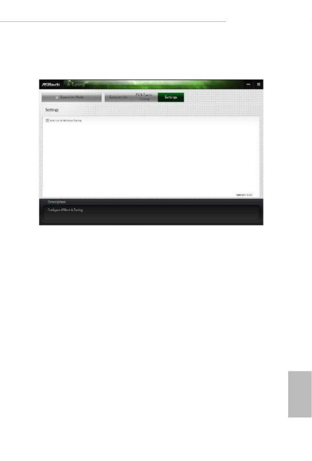
Settings
Congure ASRock A-Tuning. Click to select "Auto run at Windows Startup" if you
want A-Tuning to be launched when you start up the Windows operating system.

English
26
3.3 ASRock Live Update & APP Shop
e ASRock Live Update & APP Shop is an online store for purchasing and
downloading soware applications for your ASRock computer. You can quickly and
easily install various apps and support utilities. With ASRock Live Update & APP
Shop, you can optimize your system and keep your motherboard up to date simply
with a few clicks.
Double-click on your desktop to access ASRock Live Update & APP Shop
utility.
*You need to be connected to the Internet to download apps from the ASRock Live Update & APP Shop.
3.3.1 UI Overview
Category Panel: e category panel contains several category tabs or buttons that
when selected the information panel below displays the relative information.
Information Panel: e information panel in the center displays data about the
currently selected category and allows users to perform job-related tasks.
Hot News: e hot news section displays the various latest news. Click on the image
to visit the website of the selected news and know more.
Information Panel
Hot News
Category Panel
English
27
H310CM-HG4
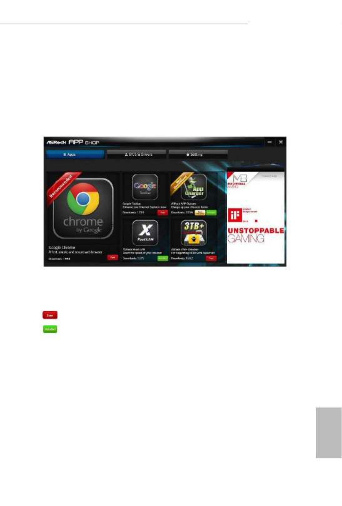
3.3.2 Apps
When the "Apps" tab is selected, you will see all the available apps on screen for you
to download.
Installing an App
Step 1
Find the app you want to install.
e most recommended app appears on the le side of the screen. e other various
apps are shown on the right. Please scroll up and down to see more apps listed.
You can check the price of the app and whether you have already intalled it or not.
- e red icon displays the price or "Free" if the app is free of charge.
- e green "Installed" icon means the app is installed on your computer.
Step 2
Click on the app icon to see more details about the selected app.
Termékspecifikációk
| Márka: | Asrock |
| Kategória: | alaplap |
| Modell: | H310CM-HG4 |
Szüksége van segítségre?
Ha segítségre van szüksége Asrock H310CM-HG4, tegyen fel kérdést alább, és más felhasználók válaszolnak Önnek
Útmutatók alaplap Asrock

25 Március 2025
13 Január 2025
13 Január 2025
12 Január 2025
2 Január 2025
28 December 2024
14 Október 2024
10 Október 2024
4 Október 2024
3 Október 2024
Útmutatók alaplap
- alaplap Sharkoon
- alaplap Gigabyte
- alaplap Asus
- alaplap Supermicro
- alaplap Biostar
- alaplap MSI
- alaplap NZXT
- alaplap ECS
- alaplap Evga
- alaplap Intel
- alaplap Foxconn
- alaplap Advantech
- alaplap Elitegroup
- alaplap EPoX
Legújabb útmutatók alaplap

9 Április 2025
9 Április 2025
3 Április 2025
3 Április 2025
3 Április 2025
3 Április 2025
2 Április 2025
2 Április 2025

31 Március 2025
27 Március 2025