Használati útmutató Asrock FM2A88X Pro3+
Olvassa el alább 📖 a magyar nyelvű használati útmutatót Asrock FM2A88X Pro3+ (145 oldal) a alaplap kategóriában. Ezt az útmutatót 4 ember találta hasznosnak és 2 felhasználó értékelte átlagosan 4.5 csillagra
Oldal 1/145
Version 1.0
Published August 2014
Copyright©2014 ASRock INC. All rights reserved.
Copyright Notice:
No part of this documentation may be reproduced, transcribed, transmitted, or
translated in any language, in any form or by any means, except duplication of
documentation by the purchaser for backup purpose, without written consent of
ASRock Inc.
Products and corporate names appearing in this documentation may or may not
be registered trademarks or copyrights of their respective companies, and are used
only for identication or explanation and to the owners’ benet, without intent to
infringe.
Disclaimer:
Specications and information contained in this documentation are furnished for
informational use only and subject to change without notice, and should not be
constructed as a commitment by ASRock. ASRock assumes no responsibility for
any errors or omissions that may appear in this documentation.
With respect to the contents of this documentation, ASRock does not provide
warranty of any kind, either expressed or implied, including but not limited to
the implied warranties or conditions of merchantability or tness for a particular
purpose.
In no event shall ASRock, its directors, ocers, employees, or agents be liable for
any indirect, special, incidental, or consequential damages (including damages for
loss of prots, loss of business, loss of data, interruption of business and the like),
even if ASRock has been advised of the possibility of such damages arising from any
defect or error in the documentation or product.
e terms HDMI™ and HDMI High-Denition Multimedia Interface, and the HDMI
logo are trademarks or registered trademarks of HDMI Licensing LLC in the United
States and other countries.
is device complies with Part 15 of the FCC Rules. Operation is subject to the following
two conditions:
(1) this device may not cause harmful interference, and
(2) this device must accept any interference received, including interference that
may cause undesired operation.
CALIFORNIA, USA ONLY
e Lithium battery adopted on this motherboard contains Perchlorate, a toxic substance
controlled in Perchlorate Best Management Practices (BMP) regulations passed by the
California Legislature. When you discard the Lithium battery in California, USA, please
follow the related regulations in advance.
“Perchlorate Material-special handling may apply, see www.dtsc.ca.gov/hazardouswaste/
perchlorate”
ASRock Website: http://www.asrock.com

1
English
FM2A88X Pro3+
Motherboard Layout
SOCKE FM2bT
2 31
21
Su per
I/O
CMOS
BATTERY
PC IE1
LAN
AUDIO
CODEC
CP U_F AN1 C PU _F AN2
64 M b
BIO S
FM2A88X +Pro3
PC IE4
PC IE2
PCI1
PCI2
1
CLR CMO S 1
HDLE RES ETD
PLED PWR BT N
1
PANE L 1
SPEA KER 1
1
PLE D1
1
HD_ AU DIO1
1
CO M1
1
1
USB 6_ 7
1
USB 8_ 9
Top:
LINE I N
Ce nt er :
FRON T
Bo tt om :
MIC IN
RoHS
PS2
M eou s
PS2
Ke yboard
US 3.B 0
T: 2USB
B: USB 3
RJ- 45 LAN
US 2.B 0
T: 4USB
B: USB 5
CHA_ FAN1
PC IE3
PC Ex pressI 03.
US 2.B 0
T: 0USB
B: USB 1
ATX 112V
DDR3_A1 (64 bit, 240-pin module)
DDR3_A2 (64 bit, 240-pin module)
DDR3_B1 ( 64 bit, 240- pin module)
DDR3_B2 ( 64 bit, 240- pin module)
4 5
ATXPWR1
6
CH A_ N 2FA
CHA _FA N3
PWR_ FA N1
23
24
22
8
SAT A_ 1_ 2
12
SAT A_ 3_ 4
11
SAT A_ 5_ 6
10
1314151617181920
PC IE5
AMD
A88X
(Bolton-D4)
Chipset
SAT A_ 7_ 8
9
US B3_ 2_3
7
PC IE_ PWR 1
VGA 1
DVI1

2
English
No. Description
1 ATX 12V Power Connector (ATX12V1)
2 CPU Fan Connector (CPU_FAN1)
3 CPU Fan Connector (CPU_FAN2)
4 2 x 240-pin DDR3 DIMM Slots (DDR3_A1, DDR3_ B1)
5 2 x 240-pin DDR3 DIMM Slots (DDR3_A2, DDR3_B2)
6 ATX Power Connector (ATXPWR1)
7 USB 3.0 Header (USB3_2_3)
8 Chassis Fan Connector (CHA_FAN2)
9 SATA3 Connectors (SATA_7_8)
10 SATA3 Connectors (SATA_5_6)
11 SATA3 Connectors (SATA_3_4)
12 SATA3 Connectors (SATA_1_2)
13 System Panel Header (PANEL1)
14 Clear CMOS Jumper (CLRCMOS1)
15 Chassis Fan Connector (CHA _FAN3)
16 Power LED Header (PLED1)
17 Chassis Speaker Header (SPEAKER1)
18 USB 2.0 Header (USB8_9)
19 USB 2.0 Header (USB6_7)
20 COM Port Header (COM1)
21 Front Panel Audio Header (HD_AUDIO1)
22 Power Fan Connector (PWR _FAN1)
23 Chassis Fan Connector (CHA _FAN1)
24 PCIe Power Connector (PCIE_PWR1)

9
English
FM2A88X Pro3+
WARNING
Please realize that there is a certain risk involved with overclocking,
including adjusting the setting in the BIOS, applying Untied Overclocking
Technology, or using third-party overclocking tools. Overclocking may
affect your system’s stability, or even cause damage to the components
and devices of your system. It should be done at your own risk and
expense. We are not responsible for possible damage caused by
overclocking.
* For detailed product information, please visit our website: http://www.asrock.com
CAUTION!
1. Whether 2400/2133/1866/1600MHz memory speed is support-
ed depends on the CPU you adopt. If you want to adopt DDR3
2400/2133/1866/1600 memory module on this motherboard,
please refer to the memory support list on our website for the
compatible memory modules.
ASRock website http://www.asrock.com
2. Due to the operating system limitation, the actual memory size
may be less than 4GB for the reservation for system usage un-
der Windows® 10 / 8.1 / 8 / 7. For Windows® 64-bit OS with 64-
bit CPU, there is no such limitation. You can use ASRock XFast
RAM to utilize the memory that Windows
® cannot use.
3. allows you to wake up this system from remote Wake-On-WAN
mobile devices, such as smart phones, tables, or other PCs.
It needs third-party softwares and applications to utilize this
feature. Please visit our website for Home Cloud topic.
Certica-
tions
• FCC, CE, WHQL
• ErP/EuP ready (ErP/EuP ready power supply is
required)

10
English
2. Installation
This is an ATX form factor motherboard. Before you install the motherboard, study
the conguration of your chassis to ensure that the motherboard ts into it.
Pre-installation Precautions
Take note of the following precautions before you install motherboard
components or change any motherboard settings.
Before you install or remove any component, ensure that the
power is switched off or the power cord is detached from the
power supply. Failure to do so may cause severe damage to the
motherboard, peripherals, and/or components.
1. Unplug the power cord from the wall socket before touching any
component.
2. To avoid damaging the motherboard components due to static elec-
tricity, NEVER place your motherboard directly on the carpet or the
like. Also remember to use a grounded wrist strap or touch a safety
grounded object before you handle components.
3. Hold components by the edges and do not touch the ICs.
4. Whenever you uninstall any component, place it on a grounded anti-
static pad or in the bag that comes with the component.
5. When placing screws into the screw holes to secure the mother-
board to the chassis, please do not over-tighten the screws! Doing
so may damage the motherboard.
11
English
FM2A88X Pro3+
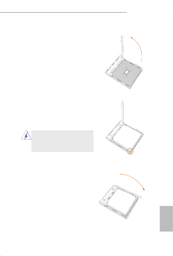
2.1 CPU Installation
Step 1. Unlock the socket by lifting the lever up
to a 90o angle.
Step 2. Position the CPU directly above the
socket such that the CPU corner with
the golden triangle matches the socket
corner with a small triangle.
Step 3. Carefully insert the CPU into the
socket until it ts in place.
The CPU ts only in one correct
orientation. DO NOT force the CPU
into the socket to avoid bending of
the pins.
Step 4. When the CPU is in place, press it
rmly on the socket while you push
down the socket lever to secure the
CPU. The lever clicks on the side tab
to indicate that it is locked.

12
English
2.2 Installation of CPU Fan and Heatsink
After you install the CPU into this motherboard, it is necessary to install a
larger heatsink and cooling fan to dissipate heat. You also need to spray
thermal grease between the CPU and the heatsink to improve heat dis-
sipation. Make sure that the CPU and the heatsink are securely fastened
and in good contact with each other. Then connect the CPU fan to the
CPU FAN connector (CPU_FAN1 and CPU_FAN2, see Page 1, No. 2
and No. 3). For proper installation, please kindly refer to the instruction
manuals of the CPU fan and the heatsink.

13
English
FM2A88X Pro3+
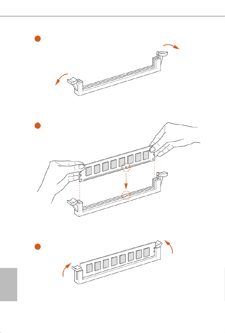
2.3 Installation of Memory Modules (DIMM)
This motherboard provides four 240-pin DDR3 (Double Data Rate 3) DIMM
slots, and supports Dual Channel Memory Technology.
Dual Channel Memory Conguration
The DIMM only ts in one correct orientation. It will cause permanent dam-
age to the motherboard and the DIMM if you force the DIMM into the slot at
incorrect orientation.
Priority DDR3_A1 DDR3_A2 DDR3_B1 DDR3_B2
1Populated Populated
2 Populated Populated
3Populated Populated Populated Populated
1. For dual channel conguration, you always need to install identical (the
same brand, speed, size and chip-type) DDR3 DIMM pairs.
2. It is unable to activate Dual Channel Memory Technology with only one or
three memory module installed.
3. It is not allowed to install a DDR or DDR2 memory module into a DDR3
slot; otherwise, this motherboard and DIMM may be damaged.
4. If you adopt DDR3 2400/2133/1866/1600 memory modules on this moth-
erboard, it is recommended to install them on DDR3_A2 and DDR3_B2
slots.
14
English
1
2
3

15
English
FM2A88X Pro3+
2.4 Expansion Slots (PCI and PCI Express Slots)
There are 2 PCI slots and 5 PCI Express slots on this motherboard.
PCI Slots: PCI slots are used to install expansion cards that have the 32-bit PCI
interface.
PCIE Slots:
PCIE1 / PCIE2 / PCIE3 (PCIe 2.0 p16-x1 slot) is used for PCI Express cards
with p16-x1 lane width cards
PCIE4 (PCIe 3.0 x16 slot) is used for PCI Express x16 lane width
graphics cards
PCIE5 (PCIe 2.0 x16 slot) is used for PCI Express p16-x4 lane width cards
PCIe Slot Congurations
For a better thermal environment, please connect a chassis fan to the moth-
erboard’s chassis fan connector (CHA_FAN1, CHA_FAN2, or CHA_FAN3)
when using multiple graphics cards.
Before installing an expansion card, please make sure that the power supply
is switched off or the power cord is unplugged. Please read the documenta-
tion of the expansion card and make necessary hardware settings for the card
before you start the installation.
PCIE4 PCIE5
Single Graphics Card x16 N/A
Two Graphics Cards in
CrossFireXTM Mode x16 x4

16
English
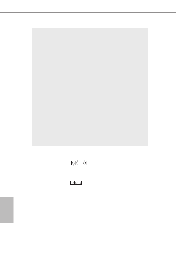
2.5 Jumpers Setup
The illustration shows how jumpers are
setup. When the jumper cap is placed on
pins, the jumper is “Short”. If no jumper cap
is placed on pins, the jumper is “Open”. The
illustration shows a 3-pin jumper whose
pin1 and pin2 are “Short” when jumper cap
is placed on these 2 pins.
Jumper Setting Description
Clear CMOS Jumper
(CLRCMOS1)
(see p.1, No. 14)
Note: CLRCMOS1 allows you to clear the data in CMOS. To clear and reset the
system parameters to default setup, please turn off the computer and unplug
the power cord from the power supply. After waiting for 15 seconds, use a
jumper cap to short pin2 and pin3 on CLRCMOS1 for 5 seconds. However,
please do not clear the CMOS right after you update the BIOS. If you need
to clear the CMOS when you just nish updating the BIOS, you must boot
up the system rst, and then shut it down before you do the clear-CMOS ac-
tion. Please be noted that the password, date, time, user default prole, 1394
GUID and MAC address will be cleared only if the CMOS battery is removed.
Clear CMOSDefault

17
English
FM2A88X Pro3+
2.6 Onboard Headers and Connectors
Onboard headers and connectors are NOT jumpers. Do NOT place
jumper caps over these headers and connectors. Placing jumper caps
over the headers and connectors will cause permanent damage of the
motherboard!
USB 2.0 Headers Besides four default USB 2.0
(9-pin USB6_7)
ports on the I/O panel, there
(see p.1 No. 19)
are two USB 2.0 headers on
(9-pin USB8_9)
this motherboard. Each USB 2.0
(see p.1 No. 18)
header can support two USB
2.0 ports.
Serial ATA3 Connectors These eight Serial ATA3
(SATA_1_2: see p.1, No. 12)
(SATA3) connectors support
(SATA_3_4: see p.1, No. 11) SATA data cables for internal
(SATA_5_6: see p.1, No. 10)
storage devices. The current
(SATA_7_8: see p.1, No. 9)
SATA3 interface allows up to
6.0 Gb/s data transfer rate.
DUMMY
GND
GND
P+
P-
USB_PWR
P+
P-
U RSB _ PW
1
SATA_5_6 SATA_7_8SATA_3_4SATA_1_2
USB 3.0 Header Besides two default USB 3.0
(19-pin USB3_2_3)
ports on the I/O panel, there is
(see p.1 No. 7)
one USB 3.0 header on this
motherboard. This USB 3.0
header can support two USB 3.0
ports.
1
In tA_ PB_ D+
Dummy
In tA_ PB_ D-
GND
In tA_ PB_ SST X+
GND
In tA_ PB_ SST X-
In tA_ PB_ SSRX+
In tA_ PB_ SSRX-
Vbu sVbu s
Vbu s
In tA_PA_SSRX-
In tA_PA_SSRX+
GND
In tA_PA_SST X-
In tA_PA_SST X+
GND
In tA_PA_D-
In tA_PA_D+

18
English
Front Panel Audio Header This is an interface for the front
(9-pin HD_AUDIO1) panel audio cable that allows
(see p.1 No. 21)
convenient connection and
control of audio devices.
J_SENSE
OUT2_L
1
MIC_RET
PRESENCE#
GND
OUT2_R
MIC2_R
MIC2_L
OUT_RET
System Panel Header This header accommodates
(9-pin PANEL1) several system front panel
(see p.1 No. 13)
functions.
GND
R #ES ET
PWRBT N#
PLE D-
PLE D+
GND
HD LE D-
HD LE D+
1
GND
1. High Denition Audio supports Jack Sensing, but the panel wire on
the chassis must support HDA to function correctly. Please follow the
instruction in our manual and chassis manual to install your system.
2. If you use AC’97 audio panel, please install it to the front panel audio
header as below:
A. Connect Mic_IN (MIC) to MIC2_L.
B. Connect Audio_R (RIN) to OUT2_R and Audio_L (LIN) to OUT2_L.
C. Connect Ground (GND) to Ground (GND).
D. MIC_RET and OUT_RET are for HD audio panel only. You don’t
need to connect them for AC’97 audio panel.
E. To activate the front mic.
For Windows
® 8.1 / 8.1 64-bit / 8 / 8 64-bit / 7 / 7 64-bit OS:
Go to the “FrontMic” Tab in the Realtek Control panel. Adjust
“Recording Volume”.
Connect the power switch, reset switch and system status indicator
on the chassis to this header according to the pin assignments below.
Note the positive and negative pins before connecting the cables.
PWRBTN (Power Switch):
Connect to the power switch on the chassis front panel. You may con-
gure the way to turn off your system using the power switch.
RESET (Reset Switch):
Connect to the reset switch on the chassis front panel. Press the reset
switch to restart the computer if the computer freezes and fails to per-
form a normal restart.

21
English
FM2A88X Pro3+
Serial port Header This COM1 header supports a
(9-pin COM1) serial port module.
(see p.1 No. 20)
CCT S # 1
RRT S # 1
DD S R# 1
DD T R# 1
RRX D 1
GND
TTX D1
DD C D# 1
1
RRI # 1
ATX 12V Power Connector Please connect an ATX 12V
(8-pin ATX12V1) power supply to this connector.
(see p.1 No. 1)
Though this motherboard provides 8-pin ATX 12V power connector, it can still work
if you adopt a traditional 4-pin ATX 12V power supply. To use the
4-pin ATX power supply, please plug your power supply along with
Pin 1 and Pin 5.
4-Pin ATX 12V Power Supply Installation
8 5
4 1
PCIe Power Connector
(4-pin PCIE_PWR1)
(see p.1, No. 24)
Please connect a 4 pin molex
power cable to this connector
when more than three
graphics cards are installed.

22
Deutsch
1. Einführung
Wir danken Ihnen für den Kauf des ASRock Motherboard, ein zu-FM2A88X Pro3+
verlässiges Produkt, welches unter den ständigen, strengen Qualitätskontrollen von
ASRock gefertigt wurde. Es bietet Ihnen exzellente Leistung und robustes Design,
gemäß der Verpflichtung von ASRock zu Qualität und Halbarkeit. Diese Schnel-
linstallationsanleitung führt in das Motherboard und die schrittweise Installation
ein. Details über das Motherboard nden Sie in der Bedienungsanleitung auf der
Support-CD.
Da sich Motherboard-Spezikationen und BIOS-Software verändern
können, kann der Inhalt dieses Handbuches ebenfalls jederzeit geändert
werden. Für den Fall, dass sich Änderungen an diesem Handbuch
ergeben, wird eine neue Version auf der ASRock-Website, ohne weitere
Ankündigung, verfügbar sein. Die neuesten Grakkarten und unterstützten
CPUs sind auch auf der ASRock-Website aufgelistet.
ASRock-Website: http://www.asrock.com
Wenn Sie technische Unterstützung zu Ihrem Motherboard oder spezische
Informationen zu Ihrem Modell benötigen, besuchen Sie bitte unsere
Webseite:
www.asrock.com/support/index.asp
1.1 Kartoninhalt
ASRock Motherboard (ATX-Formfaktor)FM2A88X Pro3+
ASRock SchnellinstallationsanleitungFM2A88X Pro3+
ASRock Support-CD FM2A88X Pro3+
Zwei Serial ATA (SATA) -Datenkabel (optional)
Ein I/O Shield

23
Deutsch
FM2A88X Pro3+
1.2 Spezikationen
Platform • ATX-Formfaktor
• Alle Feste Kondensatordesign
• PCB mit hochverdichtetem Glasfasergewebe
CPU • Unterstützt Prozessoren für Sockel FM2+ (95 W) / FM2
(100 W)
Chipsatz • AMD A88X (Bolton-D4)
• 4 + 2-Stromphasendesign
Speicher • Unterstützung von Dual-Kanal-Speichertechnologie
• 4 x Steckplätze für DDR3
• Unterstützt DDR3 2400+(OC)/2133/1866/1600/1333/
1066 non-ECC, ungepufferter Speicher
• Max. Kapazität des Systemspeichers: 64GB
• Unterstützt Intel® Extreme Memory Prole (XMP)1.3/1.2
• Unterstützt AMDs Memory Prole Technology (AMP)
bis AMP 2400
Erweit-
erungs-
steckplä-
tze
• 1 x PCI Express 3.0 x16-Steckplätze (PCIE4: x16-
Modus)
* PCIE 3.0 wird nur mit FM2+-Prozessor unterstützt.FM2-
Prozessor unterstützt nur PCIE 2.0.
• 1 x PCI Express 2.0 x16-Steckplatz (PCIE5: x4-Modus)
• 3 x PCI Express 2.0 x1-Steckplätze
• 2 x PCI -Steckplätze
• Unterstützt AMD Quad CrossFireXTM , CrossFireXTM und
duale Gra kkarten
Onboard-
VGA
• Integrierte Grakkarte der AMD Radeon
TM R7/R5-Serie
in APU der A-Serie
• DirectX 11.1, Pixel Shader 5.0 mit FM2+-Prozessor.
DirectX 11, Pixel Shader 5.0 mit FM2-Prozessor.
• Maximal gemeinsam genutzter Speicher 2GB
• Doppel-VGA Ausgabe: unterstützt DVI-D und
D-Sub Ports durch unabhängige Bildschirmanzeige
Kontrolleure

24
Deutsch
• Unterstützt Dual-link DVI-D mit einer maximalen
Auösung von 2560 x 1600 bei 60 Hz
• Unterstützt D-Sub mit einer maximalen Auösung von
1920 x 1200 bei 60 Hz
• Unterstützt AMD Steady Video
TM 2.0: Neuartige
Funktion der Videonachbearbeitung für automatische
Reduzierung von Bildschwankungen bei Heim-/Online-
Videos
• Unterstützt HDCP-Funktion mit DVI-D-Port
• Unterstutzt 1080p Blu-ray (BD) / HD-DVD-Wiedergabe
mit DVI-D-Port
Audio • 5.1 CH HD Audio (Realtek ALC662 Audio Codec)
• Unterstützt Überspannungsschutz (ASRocks
Komplettschutz vor Spannungsspitzen)
LAN • PCIE p25-x1 Gigabit LAN 10/100/1000 Mb/s
• Realtek RTL8111GR
• Unterstützt Wake-On-WAN
• Unterstützt Wake-On-LAN
• Unterstützt Schutz vor Blitzschlag/elektrostatischer Ent-
ladung (ASRocks Komplettschutz vor Spannungsspit-
zen)
• Unterstützt LAN-Kabelerkennung
• Unterstützt energieef zientes Ethernet 802.3az
• Unterstützt PXE
E/A-An-
schlüsse
an der
Rückseite
• 1 x PS/2-Mausanschluss
• 1 x PS/2-Tastaturanschluss
• 1 x D-Sub port
• 1 x DVI-D port
• 4 x Standard-USB 2.0-Anschlüsse (Unterstützt
Schutz vor elektrostatischer Entladung (ASRocks
Komplettschutz vor Spannungsspitzen))
• 2 x Standard-USB 3.0-Anschlüsse (AMD A88X
(Bolton-D4)) (Unterstützt Schutz vor elektrostatischer
Entladung (ASRocks Komplettschutz vor
Spannungsspitzen))

25
Deutsch
FM2A88X Pro3+
• 1 x RJ-45 LAN Port mit LED (ACT/LINK LED und
SPEED LED)
• HD Audiobuchse: Audioeingang / Lautsprecher vorne /
Mikrofon
Speicher • 8 x SATA 3-Anschluss mit 6,0 Gb/s, unterstützt RAID-
(RAID 0, RAID 1, RAID 5 und RAID 10), NCQ-, AHCI-
und „Hot Plugging“-Funktionen
An-
schlüsse
• 1 x COM-Anschluss-Header
• 1 x Betriebs-LED-Header
• 2 x CPUlüfter-Anschluss (1 x 4-pin, 1 x 3-pin)
• 3 x Gehäuselüfter-Anschluss (1 x 4-pin, 2 x 3-pin)
• 1 x Stromlüfter-Anschluss (3-pin)
• 1 x 24-pin ATX-Netz-Header
• 1 x 8-pin anschluss für 12V-ATX-Netzteil
• 1 x 1 PCIe-Stromanschluss
• 1 x Anschluss für Audio auf der Gehäusevorderseite
• 2 x USB 2.0-Anschlüsse (Unterstützung 4 zusätzlicher
USB 2.0-Anschlüsse) (Unterstützt Schutz vor elektro-
statischer Entladung (ASRocks Komplettschutz vor
Spannungsspitzen))
• 1 x En-tête USB 3.0 de AMD A88X (Bolton-D4) (prendre
en charge 2 ports USB 3.0 supplémentaires) (Unterstützt
Schutz vor elektrostatischer Entladung (ASRocks
Komplettschutz vor Spannungsspitzen))
BIOS • 64Mb AMIs Legal BIOS UEFI mit GUI-Unterstützung
• Unterstützung für “Plug and Play”
• ACPI 1.1-Weckfunktionen
• JumperFree-Modus
• SMBIOS 2.3.1
• DRAM, VDDP, VDDR Stromspannung Multianpassung
Hardware
Monitor
• CPU-Temperatursensor
• Motherboardtemperaturerkennung
• Drehzahlmessung für CPUlüfter
• Drehzahlmessung für Gehäuselüfter
• Geräuscharmer CPU-/Gehäuselüfter

26
Deutsch
* Für die ausführliche Produktinformation, besuchen Sie bitte unsere Website:
http://www.asrock.com
• Mehrstu ge Geschwindigkeitsteuerung für CPU-/
• Gehäuselüfter Spannungsüberwachung: +12V, +5V,
+3.3V, Vcore
Betriebs-
systeme
• Microsoft® Windows® 8.1 32-bit / 8.1 64-bit / 8 32-bit /
8 64-bit / 7 32-bit / 7 64-bit
Zerti-
zierungen
• FCC, CE, WHQL
• Prêt pour ErP/EuP (alimentation Prêt pour ErP/EuP
requise)

27
Deutsch
FM2A88X Pro3+
1.3 Einstellung der Jumper
Die Abbildung verdeutlicht, wie Jumper
gesetzt werden. Werden Pins durch
Jumperkappen verdeckt, ist der Jumper
“Gebrückt”. Werden keine Pins durch
Jumperkappen verdeckt, ist der Jumper
“Offen”. Die Abbildung zeigt einen 3-Pin
Jumper dessen Pin1 und Pin2 “Ge-
brückt” sind, bzw. es bendet sich eine
Jumper-Kappe auf diesen beiden Pins.
Jumper Einstellun Beschreibung
CMOS löschen
(CLRCMOS1, 3-Pin jumper)
(siehe S.1, No. 14)
Hinweis:
CLRCMOS1 ermöglicht Ihnen die Löschung der Daten im CMOS. Zum
Löschen und Zurücksetzen der Systemparameter auf die Standardeinrichtung
schalten Sie den Computer bitte aus und trennen das Netzkabel von der
Stromversorgung. Warten Sie 15 Sekunden, schließen Sie dann Pin2 und
Pin3 am CLRCMOS1 über einen Jumper fünf Sekunden lang kurz. Sie
sollten das CMOS allerdings nicht direkt nach der BIOS-Aktualisierung
löschen. Wenn Sie das CMOS nach Abschluss der BIOS-Aktualisierung
löschen müssen, fahren Sie zuerst das System hoch. Fahren Sie es dann
vor der CMOS-Löschung herunter. Bitte beachten Sie, dass Kennwort,
Datum, Uhrzeit, benutzerdeniertes Prol, 1394 GUID und MAC-Adresse
nur gelöscht werden, wenn die CMOS-Batterie entfernt wird.
CMOS
löschen
Default-
Einstellung

28
Deutsch
USB 2.0-Header Zusätzlich zu den vier
(9-pol. USB6_7) üblichen USB 2.0-Ports an den
(siehe S.1 - No. 19) I/O-Anschlüssen benden sich
(9-pol. USB8_9) zwei USB 2.0-
(siehe S.1 - No. 18) Anschlussleisten am
Motherboard. Pro USB 2.0-
Anschlussleiste werden zwei
USB 2.0-Ports unterstützt.
Seriell-ATA3-Anschlüsse Diese acht Serial ATA3-
(SATA_1_2: siehe S.1 - No. 12)
(SATA3-)Verbínder
(SATA_3_4: siehe S.1 - No. 11) unterstützten SATA-Datenkabel
(SATA_5_6: siehe S.1 - No. 10)
für interne
(SATA_7_8: siehe S.1 - No. 9) Massenspeichergeräte. Die
aktuelle SATA3- Schnittstelle
ermöglicht eine
Datenübertragungsrate bis
6,0 Gb/s.
1.4 Anschlüsse
Anschlussleisten sind KEINE Jumper. Setzen Sie KEINE Jumperkappen
auf die Pins der Anschlussleisten. Wenn Sie die Jumperkappen auf die
Anschlüsse setzen, wird das Motherboard permanent beschädigt!
Anschluss Beschreibung
USB 3.0-Header Neben zwei Standard-USB
(19-pol. USB3_2_3)
3.0-Ports am E/A-Panel
(siehe S.1 - No. 7)
bendet sich ein USB 3.0-
Header an diesem
Motherboard. Dieser USB 3.0-
Header kann zwei USB 3.0-
Ports unterstützen.
1
In tA_ PB_ D+
Dummy
In tA_ PB_ D-
GND
In tA_ PB_ SST X+
GND
In tA_ PB_ SST X-
In tA_ PB_ SSRX+
In tA_ PB_ SSRX-
Vbu sVbu s
Vbu s
In tA_PA_ SSRX-
In tA_PA_ SSRX+
GND
In tA_PA_ SST X-
In tA_PA_ SST X+
GND
In tA_PA_D-
In tA_PA_D+
SATA_5_6 SATA_7_8SATA_3_4SATA_1_2
DUMMY
GND
GND
P+
P-
USB_PWR
P+
P-
U RSB _ PW
1

29
Deutsch
FM2A88X Pro3+
Anschluss für Audio auf Dieses Interface zu einem
der Gehäusevorderseite Audio-Panel auf der Vorder
(9-Pin HD_AUDIO1) seite Ihres Gehäuses,
(siehe S.1 - No. 21)
ermöglicht Ihnen eine bequeme
Anschlussmöglichkeit und
Kontrolle über Audio-Geräte.
1. High Denition Audio unterstützt Jack Sensing (automatische Erkennung
falsch angeschlossener Geräte), wobei jedoch die Bildschirmverdrahtung
am Gehäuse HDA unterstützen muss, um richtig zu funktionieren.
Beachten Sie bei der Installation im System die Anweisungen in unserem
Handbuch und im Gehäusehandbuch.
2. Wenn Sie die AC’97-Audioleiste verwenden, installieren Sie diese wie
nachstehend beschrieben an der Front-Audioanschlussleiste:
A. Schließen Sie Mic_IN (MIC) an MIC2_L an.
B. Schließen Sie Audio_R (RIN) an OUT2_R und Audio_L (LIN) an OUT2_L an.
C. Schließen Sie Ground (GND) an Ground (GND) an.
D. MIC_RET und OUT_RET sind nur für den HD-Audioanschluss gedacht. Diese
Anschlüsse müssen nicht an die AC’97-Audioleiste angeschlossen werden.
E. So aktivieren Sie das Mikrofon an der Vorderseite.
Bei den Betriebssystemen Windows
® 8.1 / 8.1 64 Bit / 8 / 8 64 Bit / 7 / 7 64
Bit: Wählen Sie im Realtek-Bedienfeld die „FrontMic“ (Vorderes
Mikrofon)-Registerkarte. Passen Sie die „Recording Volume“ (Aufnahmelaut
stärke) an.
System Panel-Header Dieser Header unterstützt
(9-pin PANEL1) mehrere Funktion der
(siehe S.1 - No. 13)
Systemvorderseite.
Schließen Sie die Ein-/Austaste, die Reset-Taste und die
Systemstatusanzeige am Gehäuse an diesen Header an; befolgen Sie
dabei die nachstehenden Hinweise zur Pinbelegung. Beachten Sie die
positiven und negativen Pins, bevor Sie die Kabel anschließen.
J_SENSE
OUT2_L
1
MIC_RET
PRESENCE#
GND
OUT2_R
MIC2_R
MIC2_L
OUT_RET
GND
R #ES ET
PWRBT N#
PLE D-
PLE D+
GND
HD LE D-
HD LE D+
1
GND
30
Deutsch
PWRBTN (Ein-/Ausschalter):
Zum Anschließen des Ein-/Ausschalters an der Frontblende des Gehäu
ses. Sie können kongurieren, wie das System mit Hilfe des
Ein-/Ausschalters ausgeschaltet werden können soll.
RESET (Reset-Taste):
Zum Anschließen der Reset-Taste an der Frontblende des Gehäuses.
Mit der Reset-Taste können Sie den Computer im Falle eines Absturzes
neu starten.
PLED (Systembetriebs-LED):
Zum Anschließen der Betriebsstatusanzeige an der Frontblende des
Gehäuses. Die LED leuchtet, wenn das System in Betrieb ist. Die LED
blinkt, wenn sich das System im Ruhezustand S1 bendet. Die LED
schaltet sich aus, wenn sich das System in den Modi S3/S4 bendet
oder ausgeschaltet ist (S5).
HDLED (Festplattenaktivitäts-LED):
Zum Anschließen der Festplattenaktivitäts-LED an der Frontblende des
Gehäuses. Die LED leuchtet, wenn die Festplatte Daten liest oder
schreibt.
Das Design der Frontblende kann je nach Gehäuse variiere. Ein
Frontblendenmodul besteht hauptsächlich aus einer Ein-/Austaste, einer
Reset-Taste, einer Betriebs-LED, einer Festplattenaktivitäts-LED,
Lautsprechern, etc. Stellen Sie beim Anschließen des
Frontblendenmoduls Ihres Gehäuses an diesem Header sicher, dass die
Kabel- und Pinbelegung korrekt übereinstimmen.
Betriebs-LED-Header Bitte schließen Sie die
(3-pin PLED1) Betriebs-LED des Gehäuses
(siehe S.1 - No. 16) zur Anzeige des
Systembetriebsstatus an
diesem Header an. Die LED
leuchtet, wenn das System in
Betrieb ist. Die LED blinkt im
S1-Zustand. Im S3-/S4- oder
S5-Zustand (ausgeschaltet)
leuchtet die LED nicht.
Gehäuselautsprecher-Header Schließen Sie den
(4-pin SPEAKER1) Gehäuselautsprecher an
(siehe S.1 - No. 17) diesen Header an.
1
+5 V
DUM MY
DUM MY
SPE AKE R
1
PLED+
PLED+
PLED-

31
Deutsch
FM2A88X Pro3+
Gehäuse- und Verbinden Sie die Lüfterkabel
Stromlüfteranschlüsse mit den Lüfteranschlüssen,
(4-pin CHA_FAN1) wobei der schwarze Draht an
(siehe S.1 - No. 23)
den Schutzleiterstift
angeschlossenwird.
(3-pin CHA_FAN2)
(siehe S.1 - No. 8)
(3-pin CHA_FAN3)
(siehe S.1 - No. 15)
(3-pin PWR_FAN1)
(siehe S.1 - No. 22)
GN D
+1 2V
CH A_F AN_SPEED
FAN _SPEED_CONTROL
GND
FAN_VOLT AGE
CHA
_
FAN
_
SP EED
ATX-Netz-Header Verbinden Sie die ATX-
(24-pin ATXPWR1)
Stromversorgung mit diesem
(siehe S.1 - No. 6)
Header.
12
1
24
13
CPU-Lüfteranschluss Verbinden Sie das CPU -
(4-pin CPU_FAN1) Lüfterkabel mit diesem
(siehe S.1 - No. 2)
Anschluss und passen Sie den
schwarzen Draht dem
Erdungsstift an.
Pins 1–3 anschließen
Lüfter mit dreipoligem Anschluss installieren
Obwohl dieses Motherboard einen vierpoligen CPU-Lüfteranschluss
(Quiet Fan) bietet, können auch CPU-Lüfter mit dreipoligem Anschluss
angeschlossen werden; auch ohne Geschwindigkeitsregulierung. Wenn
Sie einen dreipoligen CPU-Lüfter an den CPU-Lüferanschluss dieses
Motherboards anschließen möchten, verbinden Sie ihn bitte mit den
Pins 1 – 3.
(3-pin CPU_FAN2)
(siehe S.1 - No. 3)
1 2 3 4
GND
+12V
CPU_
FAN_SPEED
FAN_SPEED_CONTRO
GND
CPU_FAN_SPEED
FAN_VOLT AGE

32
Deutsch
ATX 12V Anschluss Bitte schließen Sie an diesen
(8-pin ATX12V1) Anschluss die ATX 12V
(siehe S.1 - No. 1) Stromversorgung an.
COM-Anschluss-Header Dieser COM-Anschluss-
(9-pin COM1) Header wird verwendet, um
(siehe S.1 - No. 20) ein COM-Anschlussmodul zu
unterstützen.
CCTS#1
RRTS#1
DDSR#1
DDTR#1
RRXD1
GND
TTXD1
DDCD#1
1
RRI#1
PCIe-Stromanschluss
(PCIE_PWR1, vierpolig)
(siehe S.1 - No. 24)
Bitte schließen Sie
ein vierpoliges Molex-
Stromversorgungskabel an
diesen Anschluss an, wenn
mehr als drei Grakkarten
installiert sind.
Installation der 4-Pin ATX 12V Energieversorgung
Obwohl diese Hauptplatine 8-Pin ATX 12V Stromanschluss zur
Verfügung stellt, kann sie noch arbeiten, wenn Sie einen
traditionellen 4-Pin ATX 12V Energieversorgung adoptieren. Um die
4-Pin ATX Energieversorgung zu verwenden, stecken Sie bitte Ihre
Energieversorgung zusammen mit dem Pin 1 und Pin 5 ein.
8 5
4 1

Français
FM2A88X Pro3+
33
FM2A88X Pro3+
1. Introduction
Merci pour votre achat d’une carte mère ASRock , une carte mère FM2A88X Pro3+
très able produite selon les critères de qualité rigoureux de ASRock. Elle offre des
performances excellentes et une conception robuste conformément à l’engagement
d’ASRock sur la qualité et la abilité au long terme.
Ce Guide d’installation rapide présente la carte mère et constitue un guide
d’installation pas à pas. Des informations plus détaillées concernant la carte
mère pourront être trouvées dans le manuel l’utilisateur qui se trouve sur le CD
d’assistance.
Les spécications de la carte mère et le BIOS ayant pu être mis à
jour, le contenu de ce manuel est sujet à des changements sans
notication. Au cas où n’importe qu’elle modication intervenait sur ce
manuel, la version mise à jour serait disponible sur le site web
ASRock sans nouvel avis. Vous trouverez les listes de prise en
charge des cartes VGA et CPU également sur le site Web ASRock.
Site web ASRock, http://www.asrock.com
Si vous avez besoin de support technique en relation avec cette carte
mère, veuillez consulter notre site Web pour de plus amples
informations particulières au modèle que vous utilisez.
www.asrock.com/support/index.asp
1.1 Contenu du paquet
Carte mère ASRock FM2A88X Pro3+ (Facteur de forme ATX)
Guide d’installation rapide ASRock FM2A88X Pro3+
CD de soutien ASRock FM2A88X Pro3+
Deux câbles de données de série ATA (SATA) (en option)
Un I/O Panel Shield

34
Français
1.2 Spécications
Format • Facteur de forme ATX
• Accessoires de Carte mère
• PCB High Density Glass Fabric
CPU • Prend en charge les processeurs à socket FM2+
95W / FM2 100W
• Conception 4 + 2 Power Phase
Chipsets • AMD A88X (Bolton-D4)
Mémoire • Compatible avec la Technologie de Mémoire à Canal
Double
• 4 x slots DIMM DDR3
• Supporter DDR3 2400+(OC)/2133/1866/1600/1333/
1066 non-ECC, sans amortissement mémoire
• Capacité maxi de mémoire système: 64GB
• Prend en charge le pro l de mémoire extrême Intel ®
(XMP)1.3/1.2
• Prend en charge la technologie AMD Memory Prole
(Prol de mémoire AMD - AMP) jusqu’à AMP 2400
Slot
d’extension
• 1 x slots PCI Express 3.0 x16 (PCIE4 à mode x16)
* PCIE 3.0 est uniquement pris en charge le
processeur FM2+. Avec le processeur FM2, seul
PCIE 2.0 est pris en charge.
• 1 x slot PCI Express 2.0 x16 (PCIE5 à mode x4)
• 3 x slots PCI Express 2.0 x1
• 2 x slots PCI
• Support de AMD Quad CrossFireX TM, CrossFireX TM
et Dual Graphics
VGA sur
carte
• APU AMD Radeon TM R7/R5 série graphiques A-series
• DirectX 11.1, Pixel Shader 5.0 avec processeur
FM2+.DirectX 11, Pixel Shader 5.0 avec processeur
FM2.
Termékspecifikációk
| Márka: | Asrock |
| Kategória: | alaplap |
| Modell: | FM2A88X Pro3+ |
Szüksége van segítségre?
Ha segítségre van szüksége Asrock FM2A88X Pro3+, tegyen fel kérdést alább, és más felhasználók válaszolnak Önnek
Útmutatók alaplap Asrock

25 Március 2025
13 Január 2025
13 Január 2025
12 Január 2025
2 Január 2025
28 December 2024
14 Október 2024
10 Október 2024
4 Október 2024
3 Október 2024
Útmutatók alaplap
- alaplap Sharkoon
- alaplap Gigabyte
- alaplap Asus
- alaplap Supermicro
- alaplap Biostar
- alaplap MSI
- alaplap NZXT
- alaplap ECS
- alaplap Evga
- alaplap Intel
- alaplap Foxconn
- alaplap Advantech
- alaplap Elitegroup
- alaplap EPoX
Legújabb útmutatók alaplap

9 Április 2025
9 Április 2025
3 Április 2025
3 Április 2025
3 Április 2025
3 Április 2025
2 Április 2025
2 Április 2025

31 Március 2025
27 Március 2025